Hey guys. Sorry for not updating you guys about this portable game console project for an extended period of time. I have been rather busy lately.
The previous blogpost of this game console was about the Stay In game developed for the 4th Alakajam. This blogpost aims to document the update of the portable game console project since the last blogpost! :)
This project had come a long way without having an official name. From now on, "ilo musi" will be the name of this portable game console! It means "amusing device" or "playful device" or "toy" in Toki Pona language. This name is chosen mainly because it is unique, and it is meaningful. As this game console is a minimalist one, this name also map well to the ideology of minimalism of Toki Pona.
I've drawn a PCB for this project! And this is the first PCB I've ever designed in my life! I've done this PCB almost five months ago. But I didn't have the time to blog about this. :)

This PCB was designed using KiCAD. The main reason of using this PCB software is that it's FOSS. To learn drawing a PCB, I went thru the official getting started documentation of KiCAD. After going thru the tutorial, I managed to draw the PCB for the game console. It's easier than I thought it'd be. :)
I've made a mistake on designing the PCB. I messed up the pinout of the microSD card as I thought that it would be identical to full-side SD card. Then I designed the circuit based on the pin-mapping of the full-size SD card. It turns out that they're different.
Here's the pinout of full-size SD card layout in SPI mode: CS, DI, VSS1, VDD, SCLK, VSS2, DO, UNUSED, UNUSED
And here's the pinout of microSD card layout in SPI mode: UNUSED, CS, DI, VDD, SCLK, VSS, DO, UNUSED
Notice how there's an extra VSS1 in the full-size SD card. I didn't notice that and I messed up. Too bad! I realized this mistake after sending my design to the PCB fab. :'(
I asked about how much would it cost to modify the design. The PCB fab told me that it's already in production. So it wasn't possible to change the design anymore. I ordered another batch of PCB with the new design. And now I've got 10 wrong ilo musi PCBs laying around:

Oh well. Lesson learned: Review the design carefully before sending it for PCB fabrication.
With the microSD issue fixed, the current PCB is working properly. Anyway, there're still some minor issues with the PCB:
The microcontroller had been upgraded from STM32F030K6T6 to STM32F030C6T6. STM32F030C6T6 has more GPIO pins compared with STM32F030K6T6. And it is easier to upgrade to another pin-compatible microcontroller with STM32F030C6T6, which is the main reason of this change. With STM32F030C6T6, it'd be possible to upgrade the RAM and flash space of the microcontroller without modifying the PCB.
As a result of the microcontroller upgrade, the amount of spare GPIO had been increased from 12 pins to 22 pins. Now there're 22 user-accessible GPIO pins that can be accessed by the games developed for this game console! :)
In the final product, the following specs is to be expected:
The game-selection menu of ilo musi is implemented! Its purpose? You guessed it. It's used for selecting a game on the microSD card. With game selection menu, it's possible to store multiple games on the same microSD card. Then the player can choose a ROM from the microSD card and play it! The menu also load system configurations and has feature designed for the ease of game development.

As shown on the picture above, the player can choose the game using the menu. The menu can be navigated using key UP and key DOWN. Key 1 is used for starting the game, and key 2 is used for refreshing the microSD card (useful for changing the microSD card).
This portable game console supports microSD card formatted as FAT32 filesystem. The file names are shown as 8.3 filename. Directory navigation is possible.
Upon the game is selected, self-flashing would be performed. After that, the program counter would be jumped from the bootloader to the game. Then it'd be up to the game to handle what to do.
As for the procedure of new game development, first, prepare the game resources, including graphical assets and whatever needed and pack the game ROM as "DEBUGRES.IMG". After that, put the file "DEBUGRES.IMG" file somewhere on the microSD card (can be put onto the root directory). Then program the game code to the microcontroller using ISP. Then the game console would be reset. Then the developer would navigate to the directory containing the "DEBUGRES.IMG". If the file is available in the directory, the game console would not perform self-flashing and jump to the game right away. Since the self-flashing part is skipped, this allows the developer to run debugger for the source code of the game with the updated game code that the developer had just flashed using ISP without repacking the game ROM. This "DEBUGRES.IMG" feature makes the life of the game developers easier.
It is possible to perform contrast adjustment using the menu by pressing key LEFT and key RIGHT. This would adjust the brightness of the pixels on the LCD. The contrast adjustment value is stored on the option bytes of the microcontroller so that it'd persist after reboot.
Along with contrast adjustment value, the clock calibration trimming value is also stored in the option bytes. The option bytes are loaded by the menu on boot. We'll get to the clock calibration trimming value in the next section of this blogpost.
There're only two option bytes in the microcontroller. The two 5-bit calibration trimming values takes 10 bits. That leaves 6 bits for contrast adjustment, which is good enough as the range of adjustment is from -10 to +2. Needless to say, some bitwise manipulation is required to put three different values into two option bytes. And this has been taken care of. :)
In most of the cases, the internal clock just works fine. According to the datasheet of STM32F030C6T6, the main clock (HSI) of the microcontroller typically has an error of ±5% at full temperature range (and ±1% at 25°C). This 5% of error often wouldn't be a major issue. If the game is running 5% slower or faster, it'd barely be noticeable. However, for things like asynchronous communication, particularly UART, 5% of error would be an major problem. We'd want to control the error to within 2% or so for reliable UART communication. For this reason, some clock calibration mechanism is required.
I've thought about including clock calibration mechanism in the game selection menu. However, it takes quite a bit of code size for clock calibration. For this reason, I made a "game" dedicated for performing clock calibration.
A 32.768kHz crystal soldered onto the device serves as a reference clock source for performing the calibration. This crystal is assumed to have almost no error, which actually is the case because the error we're looking at would be 0.01%-ish. With this clock source, the clock calibration "game" would be able to calibrate the clock by setting the trimming values (i.e. calibration value) of the main clock (HSI) and the ADC clock (HSI14) appropriately. After that, the game would measure the frequency of the low frequency internal clock (LSI) and show it on the screen, which isn't possible to get calibrated. Finally, the calibrated values are saved to the option bytes so that it'd be loaded by the game selection menu upon the game console is booted, which makes the calibration persists across power cycles.
The software of this game console had been released!
To facilitate development of new game for this game console, I've prepared a new game template! It's a skeleton code with simple structure that would be useful for most of the games. It includes code for graphical assets loading, input handling, clean screen, frame limiting and a simple game object management library.
The Github repository containing the template game for ilo musi can be found here
A few Python scripts were developed to facilitate working with custom music, graphic and ROM format of ilo musi.
The Github repository containing the Python scripts can be found here
The bootloader is the core of the game console. It contains the game menu and the system library of the game, which all game ROMs would depend on.
The Github repository containing the bootloader and game ROMs can be found here. Currently only the binary is released because there are probably still some bugs in the bootloader. The source code of the bootloader will be eventually made available.
Since I'm done with freelancing, I've got two day job offers. To my surprise, the employment agreements of both companies have a clause saying that the copyright of all work I do while I'm employed would go to the company. The local law here say that the copyright of the stuffs that employees do during "course of employment" would go to the employer, and it'd go to the author otherwise. It means that I'd hold the copyright of hobbyist projects that I work outside work hours. But I'm not sure if the agreement would override the law.
For the existing work that I've done on this project, the copyright is definitely mine. To avoid legal dispute, the development of this game console had been suspended since I've got the day job. I'm trying to come up with an agreement on copyright arrangement of this project with my employer. My employer had verbally agreed that I'd hold the copyright of this project. But still, the paperwork isn't done yet. Hopefully everything would go thru.
In case of non-agreement on paperwork, I could just distribute this game console anyway. Despite that limitations stated above, this game console is currently perfectly playable. So it's possible to distribute it without any further copyrightable development work. Another way to do that is to hand over this project to someone else. Someone had expressed interest in hacking on this project. So I'd imagine it wouldn't be difficult to look for contributors. I could also look for a new job. But the friendly coworkers, awesome culture and decent compensation of the company are just too much for me to give up. And this kind of clause is probably more than common in employment agreements. So switching to another job may not help at all.
Meanwhile, I think I may look for legal consultation from professional lawyer on the actual copyright ownership of hobbyist projects. I know that I've signed the employment agreement. However, it wouldn't make sense if all the stuffs I make outside work hours would be copyrighted by the employer. That way I technically wouldn't even be able to post any text or photo or video to any blog or chatroom or social media without infringing the copyright of my employer. And that's just bullshit. What I really need to know is if the employment agreement would override the local copyright law. If it doesn't, I'd be all good to work on this project without any new agreement with my current employer.
Anyway, the non-copyrightable work of this project can go on without any problem, including some testing that doesn't generate copyrightable material, production efficiency research and distribution of this game console.
I'll be continue working on this game console.
No copyrightable would be generated for these tasks. I can work on these straight away:
New copyrightable material would be generated for these tasks. I have to check for the copyright ownership of the stuffs that I work on before working on these, or I could ask someone else to do these for me:
I aim to get this project done by the end of this year (not including the emulator). Let's pray and hope the copyright crap would get resolved so that the development can resume. Stay tuned! :)
As I've mentioned in my previous blogpost, the clock control mechanism were implemented. But I've been too busy to blog about that. Now I've got a moment to do a write-up of the game console project about that.
The microcontroller STM32F030F4P6 is capable for running at 48Mhz. The 48Mhz system clock is generated from 8Mhz HSI clock. It's multiplied with PLL by up to 12 to generate a system clock of up to 48Mhz.
The game console will be battery-powered. Power consumption is critical to the battery life. To minimize the power consumption, we allow the game to enter sleep mode. With frame limiting, it's highly probable for the game to have some idle time before it is required to process the next frame. During that period of time, the game would enter sleep more to save power. Of course we'd disable the PLL in sleep mode to further reduce the power consumption. And that'd cause the system clock to be limited to 8Mhz when it's sleeping.
And here's a problem. There're many clocks derived from the system clock in the microcontroller. Most of them aren't very time-critical. However, for sound generation, timing is very important. Otherwise the sound generated would be distorted.
There're two causes of sound distortion. One is the selection of using, or not using PLL. Another is modification of timer prescaler. It's empirically determined that the sound distortion caused by toggling the state of usage of PLL is negligible. However, changing the timer prescaler does affect the sound quality for quite a bit.
Since changing the timer prescaler would affect the sound quality, we'd want to avoid that. Unfortunately, if we want to preserve the value of the timer prescaler, and if we still want to enter sleep mode to save power, the maximum possible clock would be limited 32Mhz instead of 48Mhz.
Here's the reason behind it: The timer clock can be calculated with this (overly simplified) equation:
(timer clock) = (system clock) / (APB1 prescaler [including the x2 mechanism]) / (timer prescaler + 1)
Timer clock has to be a multiple of 8. APB1 prescaler has to be power of two. Timer prescaler can be any integer.
Since we need to enter sleep mode, we have to set the system clock to 8Mhz at some point of the program. Let's assume that we set the APB1 prescaler=1 and timer prescaler=3 at 8Mhz. So (timer clock) = 8Mhz / 1 / (3+1) = 2Mhz.
If we want to maintain the same timer clock without changing the timer prescale at 32Mhz, we could easily do that by just changing the APB1 prescaler to 4. So we get (timer clock) = 32Mhz / 4 / (3+1) = 2Mhz, that's still 2Mhz. Therefore, the sound quality would be good at 32Mhz.
However, things get tricky if we want to maintain the same timer clock as 8Mhz at 48Mhz. If we aren't changing the timer prescaler, we'd need to pick APB1 prescaler=6. However, APB1 prescaler has to be a power of two. So it has to be rounded to APB1 prescaler=8. Then we'd be forced to change the timer prescaler from 3 to 2 in order to maintain the timer clock. So we get (timer clock) = 48Mhz / 8 / (2+1) = 2Mhz. However, the switching of timer prescaler will cause noticable sound distortion as shown below:
32Mhz without frame limiting, no sound distortion:
32Mhz with frame limiting, negligible sound distortion:
48Mhz without frame limiting, no sound distortion:
48Mhz with frame limiting, noticable sound distortion:
Our solution is to let the game itself decide to use 32Mhz or 48Mhz clock. If the game prefers higher sound quality, then it should stick with 32Mhz. If it wants performance, it should choose 48Mhz. If the game has sound, it's recommended to use 32Mhz as possible and switch to 48Mhz only when doing computation-intensive stuffs.
I've made a minimalist breakout game. At clock rate of 32Mhz without frame-limiting, it can achieve 40fps with around 80 bricks, and 250fps with no bricks. The recommended fps is 8~10fps because of the hardware limitation of the update rate of LCD. Since the max fps is much higher than the target fps, the game console can save quite a lot of power by doing the frame-limiting to 8~10fps with the use of sleep mode. :)
It's very simple. There's just one API call that modifies the clock system. That's:
If wakeUpToBoostMode is true, it'd enter 48Mhz mode after the end of the sleep. Otherwise that'd be 32Mhz.
And it has a few other API calls for querying the status of the clock system:
Clock Control System is mainly used for frame-limiting and saving power. In the game, there's a main loop. The game should call systemSleep() after the end of processing of each frame.
Here's the typical usage inside the main loop:
The following features were implemented. But I'm saving them for the coming blogpost:
I'll be working on the following stuffs:
Stay tuned. I'll make another blogpost soon! :)
The graphic system of the portable game console project is implemented! In addition, the clock control and power saving stuffs are also implemented. This blog post focus on Graphic System. I'll save other stuffs for my next blog post.
Double buffering isn't used in this procedure:
I've modified the sample program that I made for testing storage system, input system and synth system. Now that it's also capable for testing the new graphic system!
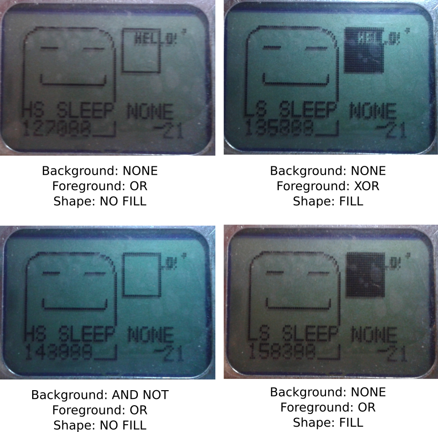
The updated sample program draws a lot of stuffs on the LCD, including a background image loaded from a resource in the ROM, a square, and system information like system tick, clock frequency and sleep mode.
In the updated sample program, the drawing mode of the square can be configured. Here's a few photo comparing some of the available the drawing modes:
Due to flash space constraint, some graphical features were removed. They include ellipse, triangle, line and dot drawing support. :(
We have 16kB of flash in total. Currently the bootloader and library takes 10kB, which is taking more space than the originally planned 8kB. It'd be even worse if these features were enabled. :(
Fortunately, it's still possible to draw those shapes by implementing the drawing function in the game itself.
I've already implemented the following features. However, these features deserve another blog post. I'll blog about them later.
I'll be working on the following stuffs:
That's it for now. I'll update you guys for any progress! :)
And I guess I'm going to take a short break from this project. I'm going to work on a piece of music!
Hey guys! The storage system of my portable game console is implemented!
It seems to be dumb to save the save content right inside the ROM file. I don't really have a choice because of the limitation of the FAT library. :(
My original idea was to have two files. One is the ROM file. Another is the save file. The save file is dynamically created by the game by using the API Calls.
However, when I tried to create the file by using the function pf_write() of the FAT library, it didn't work. Then I looked into the documentation and found out this restriction:
Alright. Then I had come up with three ideas. They're:
Using another FAT library takes a lot of work. Pre-creating a save file on the SD card would bring quite a bit of nuisance to the player because the player would have to manually paste the save file to the SD card in addition of the ROM file. So it's apparently to me that storing the save file content right inside the ROM would be the solution to go.
Since the restriction of the file-writing function is "Cannot create file. Only existing file can be written", everything should be working after saving the content right inside the ROM, right?
It turned out that I was mistaken. When I tried writing something on the SD card, the offset of the content being written was wrong! And some of the content were corrupted by zeros. Why?
After reading the documentation again, I've found out why. The library has a function for reading from file, and another function for writing to file. The function for reading works with any file offset. However, the function for writing only works properly if the seek offset of the file is aligned to 512 bytes. Otherwise, the offset would be rounded down to the closest 512-bytes. In addition of that, the number of bytes written are padded with zeros to 512 bytes.
The solution? Simple! Just align the offset of each resources to 512 bytes and pad them.
Here's the file format of the ROM of the game console.
Offset      Size    Description
0           3       Magic number
3           1       ROM file format version
4           32      Name of the game. NULL-terminated.
36          32      Author of the game. NULL-terminated.
68          256     Game Description. NULL-terminated.
324         700     Reserved
1024+8*N    4       Resource offset in file. N is from 0~255.
1024+8*N+4  4       Resource length. N is from 0~255. Can be zero.
3072        varies  The content of the resources. Each resources are aligned to 512 bytes.
The python script takes a CSV input file and generate the ROM. The CSV file looks like this:
NAME,Name of the game goes here
AUTHOR,Sadale.net
DESCRIPTION,Description of the game goes here
0,assets/game.bin
1,assets/level1.map
2,assets/level2.map
128,assets/titleScreen.graphic
254,[1024]
It's rather obvious what does the CSV do except the last line. For the resource #254, it allocates a resource that contains 1024 bytes of zero. It's useful for allocating space for save file of the game.
It's simple. There're only three functions.
It's rather intuitive. I guess I don't need to explain it here. :P
To demonstrate that the storage system is working, I've developed a test program. The program is capable for playing three kind of sound with configurable duty cycle. The function of the buttons are shown below:
Click here and see how does the code of the program looks like. Please notice that this isn't a complete project and it's not buildable without extif.h, which I'm not releasing until the completion of the software.
After saving the content of the file, here's how does the content of the ROM looks like:

As you can see above, the first byte 0x55 is the magic number. It's used for informing the program that the save data is valid.
The second one is the sound ID. The value of 0x01 refers to the second sound.
The third one is duty cycle. A value of 0x01 refers to 50% duty cycle.
After relaunching the program, the sound and the duty cycle will be loaded. I've tested it. The sound was played correctly after I pressed the Button A. :)
I'll be working on the following stuffs:
That's it for now. I'll update you guys for any progress! :)

If you know me personally, you'd probably heard of this portable game console. I have been working on this project for almost two months! I decided not to blog about this until now because I wasn't confident about the completion of this project. My main concern was the hardware design of my portable game console isn't going to work at all. Now that I've tested and proven that it's possible to do whatever I need to for this project. Therefore, it's now the right time to announce this project in this blog! :)
Introducing Portable Game Console Project! It is a minimalist, low-cost portable game console. It isn't an emulator of existing game console. It's a brand new game console system. It doesn't have a name yet. Until it's getting named, I'll just call it portable game console.
It's mostly a "because I can" project. I aim to learn stuffs from this project, including drawing PCB board, electronic design, a little bit mechanic design by drawing the case of the console, embedded programming, etc.
This is an open source project. There're already many existing game consoles. I don't think anyone would be interested in getting this one. Commercialization is out of the question. Instead, upon the completion of this project, I plan to do free giveaway of this console (and hopefully someone would be interested in developing games for this console). Waste all of the time! Lose all of the money! Hooray! :P
I haven't drawn a schematic diagram. So I'd just write down the wiring of STM32F030F4P6 to other hardware here. It's enough for anyone to reconstruct the circuit
Here's how the connection looks like on the prototype hardware:

I've never used most of these tools and software before this project.
STM32F030F4P6 is the microcontroller of this portable game console. It's a low-end ARM Cortex-M0 microcontroller.
It has 4kB of RAM and 16kB of Flash. In our design, the flash memory is split into two parts. The first part is the bootloader. The second part is the application (game). The bootloader contains the implementation of the API for accessing the LCD, sound system, buttons and SD card. The game is a playable that calls those API functions to access the hardware function of the game console.
The RAM is also split into two parts. A small part is exclusively used by the API. The other part is available for the application.
In addition to that, the bootloader will show a menu for the user to pick a game stored in the SD card. When the game is chosen, self-flashing will be performed to the application part of the flash memory. Then the BX instruction will be called to set the program counter to the starting point of the application, which will caused the game to be launched. There's, unfortunately, no protection of access. Although there's no API for that, it's technically possible for the application to, says, implement their own function to erase the SD card.
The bootloader will probably take 8kB of flash and very small amount of RAM (like 100 bytes).
The API call can be made by using a software interrupt. There's a fixed-address, 8-bytes storage inside the RAM. The API can be accessed by the application by first manipulating the content of the RAM of that address, then trigger a software interrupt. The interrupt EXTI line 15 is used for software interrupt. This design is inspired by int 80h of unix kernel.
Three functions are available:
keysSetDebouncePeriod() is used for setting the software debounce period. The longer it is, the slower the reaction time, and less noisy the response is.
For keysGetPressedState() and keysGetJustChangedState(), each bit represent the state of a button.
For keysGetPressedState(), pressed button would have its bit set to 1. The non-pressed one would be 0.
For keysGetJustChangedState(), pressed button that had changed would have its bit set to 1. Otherwise 0. For example, if the keysGetJustChangedState() of a button is 1, and the keysGetPressedState() is 0, that implies that the button was just released. After calling this function, the justChanged state of all buttons would reset to zero.
The sound system consists of two identical 1-bit synthesizer. One of them is for sound effect (foreground), another of them is for background music. Only one of them can output sound at one time. Depending on the configuration, it's possible to pause the background music while the sound effect is being played, or have the sound effect played during its effective duration, replacing the part of background music.
The sound synth has the following capability:
In addition, a musical playback format is defined for this game console, which enables the application to play music by calling an API function.
Piano uses a 12-suboctave scale, which means that each octave is divided by 12 notes.
However, in this game console, a 32-suboctave frequency scale is used instead. It means that each octave is divided by 32 notes. This game console is able to generate more fine frequency compared with piano, mainly useful for sounds effects. Since 32 isn't divisible by 12, some of the piano notes has to be substituted with a close enough frequency. Fortunately, this is not a problem because "Humans can notice a difference in pitch of about 5 to 6 cents" according to a paper by Beatus Dominik Loeffler. For a 32-suboctave system, the maximum error compared with piano note would be 64-suboctave, which is 1/64*100=1.5625 cent of error, which is far less than 5~6 cents. I've also personally listened to a piece of music played on the game console. It sounds good. So the frequency error isn't a problem. :)
During frequency sweeping, the 32-suboctave is further subdivided into 16 frequencies, forming 512-suboctaves. Each step of sweep would increase/decrease the frequency by a 512-suboctave until the final frequency is reached.
The frequency of the sound to be played is 2^(5+n/32) Hz, where n can be any value from 0 to 255.
Generation of tone requires vibration of audio signal. For a 1-bit synth, the duty cycle determines the duration of the signal to be LOW or HIGH. Let's take a 1000Hz sound wave as an example. It takes 1ms to complete a period. If the duty cycle is 50%, 0.5ms would be spent on LOW, and another 0.5ms would be spent on HIGH. If the duty cycle is 75%, the signal would be LOW for 0.25ms, and HIGH for 0.75ms.
Although this synth is 1-bit synth, it's possible to control the volume of the synth by using duty cycle. That's because the duty cycle affects the RMS value of the waveform. The closer the duty cycle to 50%, the louder the sound is.
The duty cycle can be adjusted (1-1/(n^2)) * 100%, where n can be any value from 0 to 15.
Unlike frequency, the duty cycle sweep does not have any subdivide mechanism.
The format is simple. It's a mix of command and data. Data starts with a non-zero byte. Command starts with a byte of zero. It has 6 modes. They are STOP, DF, DCF, FULL, FULL->DF, FULL->DCF.
To switch mode, set the first byte (duration) to 0, then set the second byte to the command ID. The command ID for STOP is 0, DF is 1 and so on. Here's an example of a piece of music:
uint8_t musicArray[] = {
0, 4,  //Switch to FULL->DF mode
20, 97, 97, 0, 0x11, 0, SYNTH_FREQ_SWEEP_TRIANGLE|SYNTH_DUTY_SWEEP_REPEAT_ENABLE, //Play a sound with full parameters specification and switch to DF mode
20,102, //Now that we're in DF (duration+frequency) mode. We play a sound in DF mode
65,105, //Play another sound in DF mode
20,97, //ditto
20,105, //ditto
45,102, //ditto
100,97, //ditto
0, 0 //Switch to STOP mode. It's like a NULL character for string.
};
The following functions are available:
Here's a piece of recorded music generated with the game console by using the music format:
I'll continue be developing this game console. It'll probably be completed some time in 2019. I'll update you guys about any progress! :)