The graphic system of the portable game console project is implemented! In addition, the clock control and power saving stuffs are also implemented. This blog post focus on Graphic System. I'll save other stuffs for my next blog post.
Double buffering isn't used in this procedure:
I've modified the sample program that I made for testing storage system, input system and synth system. Now that it's also capable for testing the new graphic system!
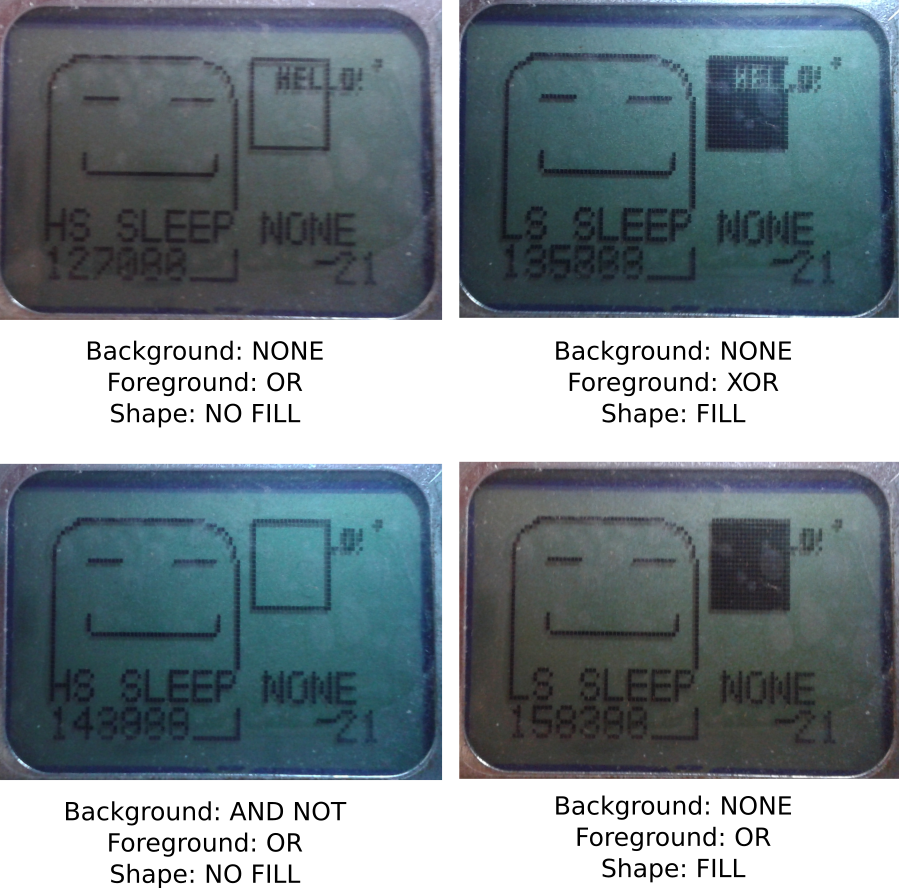
The updated sample program draws a lot of stuffs on the LCD, including a background image loaded from a resource in the ROM, a square, and system information like system tick, clock frequency and sleep mode.
In the updated sample program, the drawing mode of the square can be configured. Here's a few photo comparing some of the available the drawing modes:
Due to flash space constraint, some graphical features were removed. They include ellipse, triangle, line and dot drawing support. :(
We have 16kB of flash in total. Currently the bootloader and library takes 10kB, which is taking more space than the originally planned 8kB. It'd be even worse if these features were enabled. :(
Fortunately, it's still possible to draw those shapes by implementing the drawing function in the game itself.
I've already implemented the following features. However, these features deserve another blog post. I'll blog about them later.
I'll be working on the following stuffs:
That's it for now. I'll update you guys for any progress! :)
And I guess I'm going to take a short break from this project. I'm going to work on a piece of music!
Hey guys! The storage system of my portable game console is implemented!
It seems to be dumb to save the save content right inside the ROM file. I don't really have a choice because of the limitation of the FAT library. :(
My original idea was to have two files. One is the ROM file. Another is the save file. The save file is dynamically created by the game by using the API Calls.
However, when I tried to create the file by using the function pf_write() of the FAT library, it didn't work. Then I looked into the documentation and found out this restriction:
Alright. Then I had come up with three ideas. They're:
Using another FAT library takes a lot of work. Pre-creating a save file on the SD card would bring quite a bit of nuisance to the player because the player would have to manually paste the save file to the SD card in addition of the ROM file. So it's apparently to me that storing the save file content right inside the ROM would be the solution to go.
Since the restriction of the file-writing function is "Cannot create file. Only existing file can be written", everything should be working after saving the content right inside the ROM, right?
It turned out that I was mistaken. When I tried writing something on the SD card, the offset of the content being written was wrong! And some of the content were corrupted by zeros. Why?
After reading the documentation again, I've found out why. The library has a function for reading from file, and another function for writing to file. The function for reading works with any file offset. However, the function for writing only works properly if the seek offset of the file is aligned to 512 bytes. Otherwise, the offset would be rounded down to the closest 512-bytes. In addition of that, the number of bytes written are padded with zeros to 512 bytes.
The solution? Simple! Just align the offset of each resources to 512 bytes and pad them.
Here's the file format of the ROM of the game console.
Offset      Size    Description
0           3       Magic number
3           1       ROM file format version
4           32      Name of the game. NULL-terminated.
36          32      Author of the game. NULL-terminated.
68          256     Game Description. NULL-terminated.
324         700     Reserved
1024+8*N    4       Resource offset in file. N is from 0~255.
1024+8*N+4  4       Resource length. N is from 0~255. Can be zero.
3072        varies  The content of the resources. Each resources are aligned to 512 bytes.
The python script takes a CSV input file and generate the ROM. The CSV file looks like this:
NAME,Name of the game goes here
AUTHOR,Sadale.net
DESCRIPTION,Description of the game goes here
0,assets/game.bin
1,assets/level1.map
2,assets/level2.map
128,assets/titleScreen.graphic
254,[1024]
It's rather obvious what does the CSV do except the last line. For the resource #254, it allocates a resource that contains 1024 bytes of zero. It's useful for allocating space for save file of the game.
It's simple. There're only three functions.
It's rather intuitive. I guess I don't need to explain it here. :P
To demonstrate that the storage system is working, I've developed a test program. The program is capable for playing three kind of sound with configurable duty cycle. The function of the buttons are shown below:
Click here and see how does the code of the program looks like. Please notice that this isn't a complete project and it's not buildable without extif.h, which I'm not releasing until the completion of the software.
After saving the content of the file, here's how does the content of the ROM looks like:

As you can see above, the first byte 0x55 is the magic number. It's used for informing the program that the save data is valid.
The second one is the sound ID. The value of 0x01 refers to the second sound.
The third one is duty cycle. A value of 0x01 refers to 50% duty cycle.
After relaunching the program, the sound and the duty cycle will be loaded. I've tested it. The sound was played correctly after I pressed the Button A. :)
I'll be working on the following stuffs:
That's it for now. I'll update you guys for any progress! :)

If you know me personally, you'd probably heard of this portable game console. I have been working on this project for almost two months! I decided not to blog about this until now because I wasn't confident about the completion of this project. My main concern was the hardware design of my portable game console isn't going to work at all. Now that I've tested and proven that it's possible to do whatever I need to for this project. Therefore, it's now the right time to announce this project in this blog! :)
Introducing Portable Game Console Project! It is a minimalist, low-cost portable game console. It isn't an emulator of existing game console. It's a brand new game console system. It doesn't have a name yet. Until it's getting named, I'll just call it portable game console.
It's mostly a "because I can" project. I aim to learn stuffs from this project, including drawing PCB board, electronic design, a little bit mechanic design by drawing the case of the console, embedded programming, etc.
This is an open source project. There're already many existing game consoles. I don't think anyone would be interested in getting this one. Commercialization is out of the question. Instead, upon the completion of this project, I plan to do free giveaway of this console (and hopefully someone would be interested in developing games for this console). Waste all of the time! Lose all of the money! Hooray! :P
I haven't drawn a schematic diagram. So I'd just write down the wiring of STM32F030F4P6 to other hardware here. It's enough for anyone to reconstruct the circuit
Here's how the connection looks like on the prototype hardware:

I've never used most of these tools and software before this project.
STM32F030F4P6 is the microcontroller of this portable game console. It's a low-end ARM Cortex-M0 microcontroller.
It has 4kB of RAM and 16kB of Flash. In our design, the flash memory is split into two parts. The first part is the bootloader. The second part is the application (game). The bootloader contains the implementation of the API for accessing the LCD, sound system, buttons and SD card. The game is a playable that calls those API functions to access the hardware function of the game console.
The RAM is also split into two parts. A small part is exclusively used by the API. The other part is available for the application.
In addition to that, the bootloader will show a menu for the user to pick a game stored in the SD card. When the game is chosen, self-flashing will be performed to the application part of the flash memory. Then the BX instruction will be called to set the program counter to the starting point of the application, which will caused the game to be launched. There's, unfortunately, no protection of access. Although there's no API for that, it's technically possible for the application to, says, implement their own function to erase the SD card.
The bootloader will probably take 8kB of flash and very small amount of RAM (like 100 bytes).
The API call can be made by using a software interrupt. There's a fixed-address, 8-bytes storage inside the RAM. The API can be accessed by the application by first manipulating the content of the RAM of that address, then trigger a software interrupt. The interrupt EXTI line 15 is used for software interrupt. This design is inspired by int 80h of unix kernel.
Three functions are available:
keysSetDebouncePeriod() is used for setting the software debounce period. The longer it is, the slower the reaction time, and less noisy the response is.
For keysGetPressedState() and keysGetJustChangedState(), each bit represent the state of a button.
For keysGetPressedState(), pressed button would have its bit set to 1. The non-pressed one would be 0.
For keysGetJustChangedState(), pressed button that had changed would have its bit set to 1. Otherwise 0. For example, if the keysGetJustChangedState() of a button is 1, and the keysGetPressedState() is 0, that implies that the button was just released. After calling this function, the justChanged state of all buttons would reset to zero.
The sound system consists of two identical 1-bit synthesizer. One of them is for sound effect (foreground), another of them is for background music. Only one of them can output sound at one time. Depending on the configuration, it's possible to pause the background music while the sound effect is being played, or have the sound effect played during its effective duration, replacing the part of background music.
The sound synth has the following capability:
In addition, a musical playback format is defined for this game console, which enables the application to play music by calling an API function.
Piano uses a 12-suboctave scale, which means that each octave is divided by 12 notes.
However, in this game console, a 32-suboctave frequency scale is used instead. It means that each octave is divided by 32 notes. This game console is able to generate more fine frequency compared with piano, mainly useful for sounds effects. Since 32 isn't divisible by 12, some of the piano notes has to be substituted with a close enough frequency. Fortunately, this is not a problem because "Humans can notice a difference in pitch of about 5 to 6 cents" according to a paper by Beatus Dominik Loeffler. For a 32-suboctave system, the maximum error compared with piano note would be 64-suboctave, which is 1/64*100=1.5625 cent of error, which is far less than 5~6 cents. I've also personally listened to a piece of music played on the game console. It sounds good. So the frequency error isn't a problem. :)
During frequency sweeping, the 32-suboctave is further subdivided into 16 frequencies, forming 512-suboctaves. Each step of sweep would increase/decrease the frequency by a 512-suboctave until the final frequency is reached.
The frequency of the sound to be played is 2^(5+n/32) Hz, where n can be any value from 0 to 255.
Generation of tone requires vibration of audio signal. For a 1-bit synth, the duty cycle determines the duration of the signal to be LOW or HIGH. Let's take a 1000Hz sound wave as an example. It takes 1ms to complete a period. If the duty cycle is 50%, 0.5ms would be spent on LOW, and another 0.5ms would be spent on HIGH. If the duty cycle is 75%, the signal would be LOW for 0.25ms, and HIGH for 0.75ms.
Although this synth is 1-bit synth, it's possible to control the volume of the synth by using duty cycle. That's because the duty cycle affects the RMS value of the waveform. The closer the duty cycle to 50%, the louder the sound is.
The duty cycle can be adjusted (1-1/(n^2)) * 100%, where n can be any value from 0 to 15.
Unlike frequency, the duty cycle sweep does not have any subdivide mechanism.
The format is simple. It's a mix of command and data. Data starts with a non-zero byte. Command starts with a byte of zero. It has 6 modes. They are STOP, DF, DCF, FULL, FULL->DF, FULL->DCF.
To switch mode, set the first byte (duration) to 0, then set the second byte to the command ID. The command ID for STOP is 0, DF is 1 and so on. Here's an example of a piece of music:
uint8_t musicArray[] = {
0, 4,  //Switch to FULL->DF mode
20, 97, 97, 0, 0x11, 0, SYNTH_FREQ_SWEEP_TRIANGLE|SYNTH_DUTY_SWEEP_REPEAT_ENABLE, //Play a sound with full parameters specification and switch to DF mode
20,102, //Now that we're in DF (duration+frequency) mode. We play a sound in DF mode
65,105, //Play another sound in DF mode
20,97, //ditto
20,105, //ditto
45,102, //ditto
100,97, //ditto
0, 0 //Switch to STOP mode. It's like a NULL character for string.
};
The following functions are available:
Here's a piece of recorded music generated with the game console by using the music format:
I'll continue be developing this game console. It'll probably be completed some time in 2019. I'll update you guys about any progress! :)
I'm thinking about making an AVR (non-Arduino) portable game console. I'm evaluating the type of display to be used (including multiple 8x8 LED matrix, graphical LCD, TFT/OLED screen, alphanumeric LCD and combination of them). Then I came up with a weird idea. What if I use a alphanumeric LCD as a graphical LCD? That'd cut me quite a bit of the cost compared with using graphical LCD of the same physical dimension.
I'm a bit bored today. I feel like tinkering around with Arduino and 1602 LCD that has been around in my home. Here's what I've got as a result of hours of boredom. An Arduino-based 1602 Snake Game:
Check out the source code in this github repository!
The hardware is roughly based on this official Arduino LCD Hello World tutorial, with an addition of two push buttons.
The left push button is connected to D8, while the right push button is connected to D9. Both push buttons are pulled-down. For other connections, please refer to the schematics in the tutorial.
HD44780-compatible LCD driver supports up to 8 custom characters. By carefully defining those 8 characters, it's possible to subdivide each character into multiple "pixels". That can effectively turn the alphanumeric display into a graphical LCD display.
My design subdivides each character two rows. Each row on the character can be either empty, snake, or apple as shown below:

There're two "pixels" in each character. Each pixel can have three possible values. Therefore, the total combination is 3^2 = 9. Since one of these combination is visually empty, a space character were used to represent that. At the end only 8 custom characters are needed. So the 8 available characters in CGRAM of HD44780 are just enough for our purpose.
To reduce RAM usage, each pixel is represented by 2 bits. So a byte can store 4 pixels. Everything is cramped into a uint8_t graphicRam[GRAPHIC_WIDTH*2/8][GRAPHIC_HEIGHT]. At width of 16 and height of 4, only 16 bytes of RAM are taken for the graphic! Had I used a uint8_t for each pixel, 64 bytes of RAM would be required.
After the completion of this project, I've found other designs like spliting each character into three rows, or try making use of all pixels by generating the CGRAM on-the-fly. I'll consider using these techniques for my future projects.
To make the position looks random, we need to somehow seed the random number generator. For computer programs, we usually seed it with the current time of the machine. However, this couldn't be done on Arduino because it doesn't have a real time clock.
My solution is to make a menu screen of the game. When the user start the game, the time of the moment that the user pressed the button is used to seed the random number generator. The micros() method of Arduino Time library were used. This has the equivalent effect of using system time.
I was having fun playing with this game. I thought that it was reasonably bug-free because I had played it for a while. I've also asked one of my family members to try it out. I swear. We haven't spotted any bug.
Until I tried to record a video of the game play, something funny happened. I realized that I haven't implemented self-collision detection of the snake. I was like "Wow. How come no one had notice that earlier?". Hah. What a terrible failure!
Upon the discovery of the bug, it was fixed in no time.
Seems that using alphanumeric LCD as graphical LCD is promising. I'll consider going for this solution for the portable game console project. Of course, I won't be using Arduino for that. Arduino is good for prototyping. But it isn't as efficient as lower-level C/C++ programming.
I've played this game for many times. While it's technically possible to win, I haven't managed to do so. And I haven't tested the code of winning the game. I doubt that anyone could beat it anyway. I guess I'd just leave the code there as it is. :P

Alright. That's enough fun for today. Gotta sleep.
Hey guys! Finally I got time to blog about the technical details behind the whack-a-mole game.
Click here to view the previous part of this blog post, which is a release announcement of this game.
The game is powered by Dinbo Prototype A, which is a telephone system that I developed using SIM900A module with Raspberry Pi 3.
The schematics diagram of the system is shown below:

I knew. This system is stupid. Instead of connecting the mic and speaker of SIM900A with Raspberry Pi, GPIO is used for voice communication between them. To make the thing even funnier, an ATtiny13 is used as an ADC.
Anyway, this is just an early prototype. I just wanted to tinker around with the electronic parts that I have. And this design suits the purpose very well. More importantly, this system works. :P
Here is how does the SIM900A and ATtiny13 look like after everything is connected:

As shown above, the entire system is deployed on a breadboard.
Due to the high current requirement, multiple breadboard wires is required for the power supply of SIM900A. A capacitor is also connected between VCC and GND to smooth the voltage level over time(not shown on the outdated photo above).
Many programs were written for this system. They are ATtiny13 ADC program, serial multiplexer program, voice to socket program, and the whack-a-mole program. All of these programs are written in C.
The ATtiny13 ADC program, as its name suggests, is a program installed on the microcontoller for the purpose of converting the analog voice signal from SIM900A to time-based digital signal. When a "get sample" signal is received by PB1, it will read the analog input of PB3 send a digitized signal via PB4 to Raspberry Pi. This is the first non-Arduino embedded program I have ever developed. I had some fun on reading the specification of ATtiny13. The library avr-libc was used.
The voice to socket program is a program that converts the digitized audio signal received from the ATtiny, then send it to the whack-a-mole program using unix socket file. This is the first real time program I have developed in my life. To achieve real time execution of code, a CPU core is reserved solely for the linux process of this program.
The serial multiplexer allows multiple programs write to the serial interface of SIM900A. It redirects all of the data received from socket to the serial interface. It is adapted from this program found on Stack Overflow.
The Whack-a-mole program works by communicating with the serial multiplexer as well as the voice to socket program. It also detects DTMF tones by processing the audio signal received. Other than that, it is just like other C programs.
The source code of these programs are poorly organized. I still don't have time to package them. There are also some copyright issue on the serial multiplexer because majority of code is taken from the Stack Overflow answer with unspecified license. Therefore, I cannot release these programs too publicly. However, a copy of source code can be requested by email and they are considered on case-by-case basis.
For the final year project of my college, the development of Dinbo Prototype B is started, which will be a successor of the current system. Standard analog audio interface will be used(instead of doing the analog<->digital conversion hack using GPIOs). I also plan to solder it on a perfboard.
The library will be written in Python, which is much more flexible than C. It will be mainly designed for non-game telephone systems. However, it should be possible to make a game with it. After the completion of the library, I'll port this game to Dinbo Prototype B. I will update you guys about any news on it.