This is the second blogpost of Ilo Nanpa. You can read the first blogpost here: Ilo Nanpa (Toki Pona Calculator) - Release Announcement and Technical Details
Hey guys! I'll be distributing new units of ilo nanpa! Previously, ilo nanpa was distributed in irregular batches. From now on, I'll be shipping a batch at approximately the end of each month (unless I run out of stock).
With time-efficient production method, the time-cost of unit production is reduced by quite a lot. Therefore, I'm lowering the average donation target per unit from $30 to $20 for all of the new units produced, including international shipping fee.
For each donation made, I'd add the amount to the donation pool. For each unit shipped, I'd deduct $20 from the pool. The fund available in the donation pool will be used for giveaways, or for subsidizing those who're donating less.
For a donation of $25 per unit or above, you'll be enlisted as one of the honored donors in the official website of ilo nanpa.
If you're interested, here's the procedure of getting a unit of ilo nanpa:
If you wish to add funds to the donation pool without getting a unit of ilo nanpa, just donate to me using the donate button in the homepage of my website and contact me. The donation will be 100% used for subsidizing the recipients who are donating less or not donating (i.e. giveaway). If you wish to be named, a donation of $5 would enlist you as one of the honored donors.
The official website of ilo nanpa has been updated to show the number of units in stock, units distributed and the amount of fund available in the donation pool.
Here's the breakdown of the spending of donation for each unit:
I'd like to take this opportunity to thank all of the previous donors. With the donated amount, I've purchased new equipment, which allows me to produce ilo nanpa more efficiently.
As I'm rather new in electronics world, my current technical ability of assembling electronic parts is rather rudimentary. I've been assembling electronic devices by soldering the components onto the PCB using soldering iron one-by-one, which is extremely time consuming.
Before this project, I only had to assemble one, or perhaps a couple of prototype units for my projects. So the time inefficiency wasn't an issue. However, this had changed since the completion of the ilo napna project. I have to manually solder a handful of units of the device in order to distribute them to Toki Pona speakers. And it took me two hours to produce a unit of the device, which was dog slow. And the demand just isn't high enough to justify outsourcing the assembly process.
As the previous production method was time consuming, I looked into more time-efficient production alternatives. After some Google-Fu, I've found that solder paste stencil-based soldering is probably the way to go for the following reasons:
I've purchased the following equipment and material for experimenting with this production method:
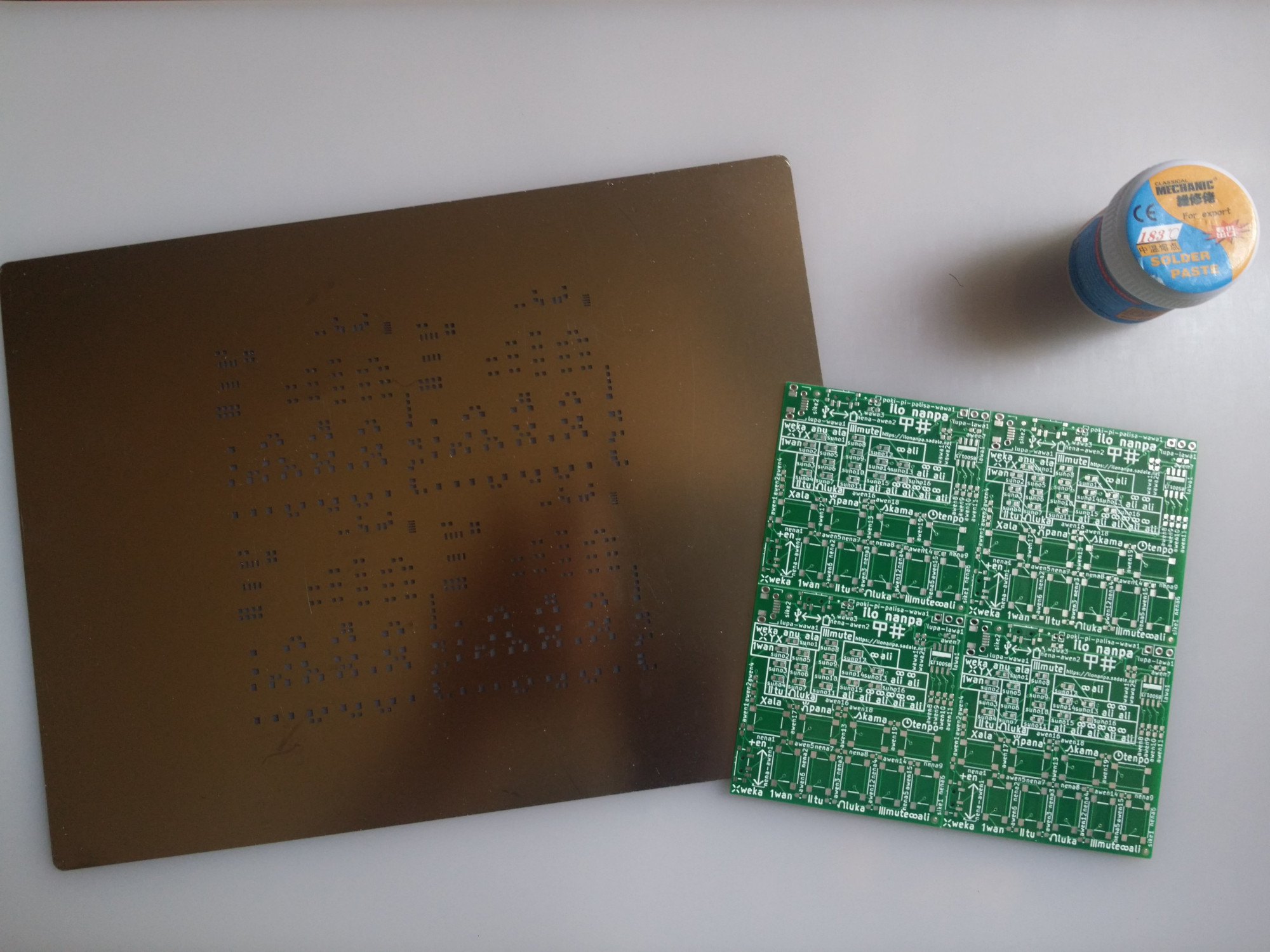
I've purchased a new batch of ilo nanpa boards. This time, the boards are panelized so that four units of the device can be produced for each PCB. After soldering them, I'd break up the PCB and I'll get four devices from a board. Here's the photo showing a jar of solder paste, panelized PCB and a stencil on a heat-resistant mat:
Not all components can be soldered by this technique. Only SMD components can be soldered in this way. Fortunately, most of the components of ilo nanpa are SMD components. The only components that require using soldering iron are the USB port, programming port and the battery holder.
I mostly just followed this solder stencil tutorial on Youtube. Except that I'm using hot air gun instead of reflow skillet for soldering the components onto the PCB.
Here's how I'm producing the devices using this new production method:
In step 2, since some spare PCBs are required for using the stencil, the 10 thought-to-be-useless wrong ilo musi boards that I ordered long time ago is now somehow useful. They're perfect to be used for holding the ilo nanpa PCB workpiece in place so that I can apply solder paste using the stencil easily.
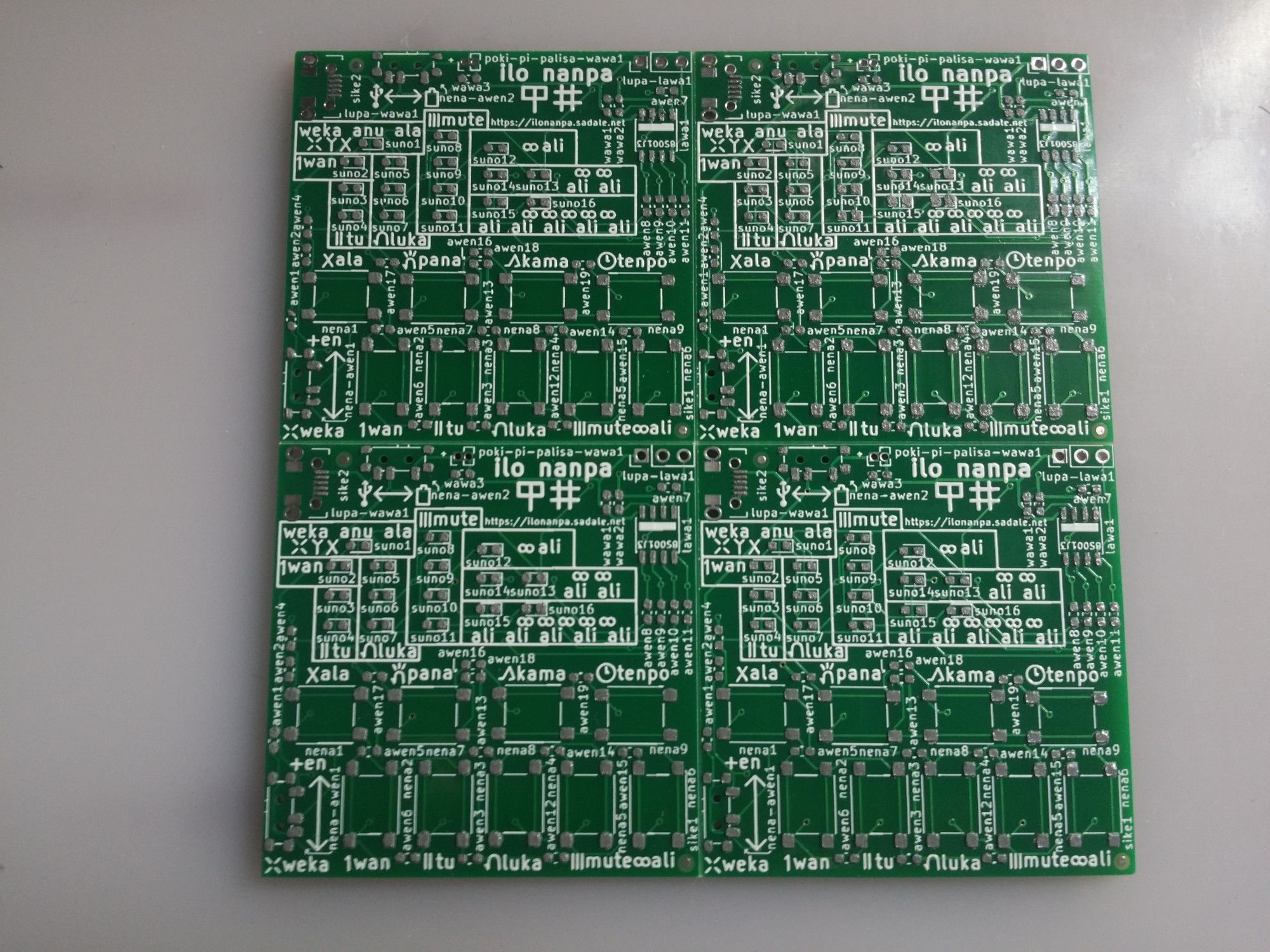
At the end of step 3, here's a photo showing a work-in-progress panelized PCB. Take a close look and you'll see there's a layer of gray solder paste applied on each of its pads:
As for the hot air gun in step 5, it's empirically found that setting the air flow to 2/8 and the temperature to 3/8 works well for soldering the components.
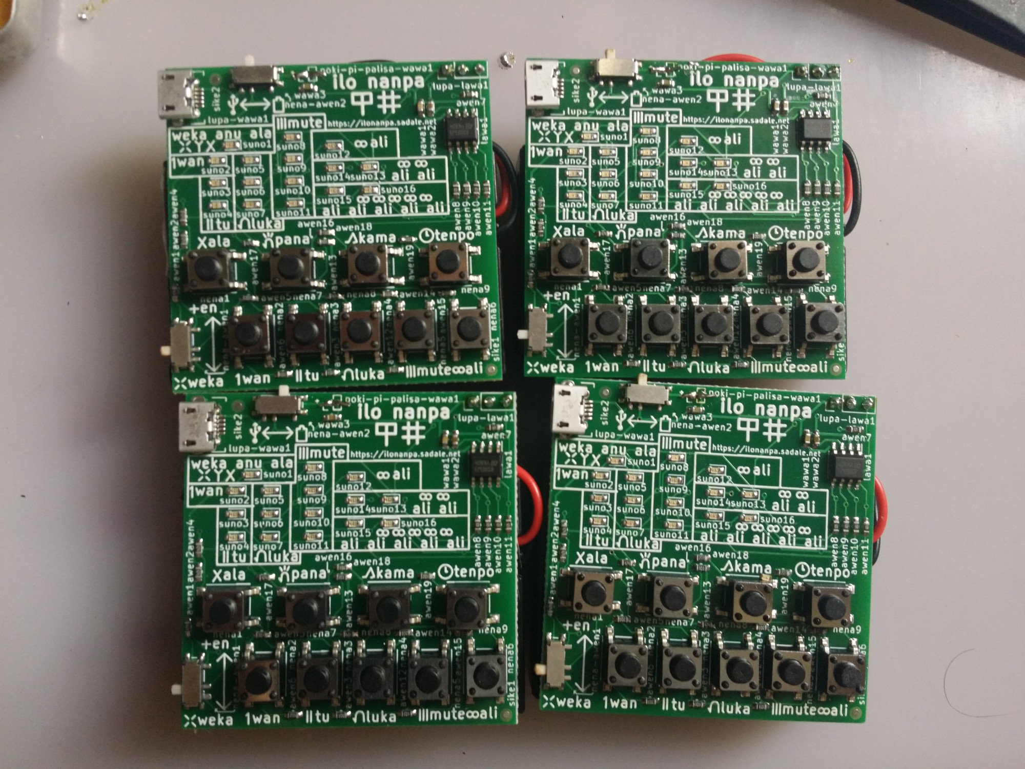
This new production method works very well. Despite that the stencil is a bit expensive, it has cut down the production time by quite a lot. Before using this method, I produced ilo nanpa at a rate of a unit per two hours. After using this method, I managed to produce four units within 2.5 hours, with an additional 0.5 hours of setup and cleanup time.
This production method is very helpful for producing several units of electronic devices in timely manner. For a demand of 20-ish units, it seems to me that it's the go-to method for production. I'm very glad to have learned it. I'll continue be using this method for small scale production.
Hey guys. Sorry for not updating you guys about this portable game console project for an extended period of time. I have been rather busy lately.
The previous blogpost of this game console was about the Stay In game developed for the 4th Alakajam. This blogpost aims to document the update of the portable game console project since the last blogpost! :)
This project had come a long way without having an official name. From now on, "ilo musi" will be the name of this portable game console! It means "amusing device" or "playful device" or "toy" in Toki Pona language. This name is chosen mainly because it is unique, and it is meaningful. As this game console is a minimalist one, this name also map well to the ideology of minimalism of Toki Pona.
I've drawn a PCB for this project! And this is the first PCB I've ever designed in my life! I've done this PCB almost five months ago. But I didn't have the time to blog about this. :)

This PCB was designed using KiCAD. The main reason of using this PCB software is that it's FOSS. To learn drawing a PCB, I went thru the official getting started documentation of KiCAD. After going thru the tutorial, I managed to draw the PCB for the game console. It's easier than I thought it'd be. :)
I've made a mistake on designing the PCB. I messed up the pinout of the microSD card as I thought that it would be identical to full-side SD card. Then I designed the circuit based on the pin-mapping of the full-size SD card. It turns out that they're different.
Here's the pinout of full-size SD card layout in SPI mode: CS, DI, VSS1, VDD, SCLK, VSS2, DO, UNUSED, UNUSED
And here's the pinout of microSD card layout in SPI mode: UNUSED, CS, DI, VDD, SCLK, VSS, DO, UNUSED
Notice how there's an extra VSS1 in the full-size SD card. I didn't notice that and I messed up. Too bad! I realized this mistake after sending my design to the PCB fab. :'(
I asked about how much would it cost to modify the design. The PCB fab told me that it's already in production. So it wasn't possible to change the design anymore. I ordered another batch of PCB with the new design. And now I've got 10 wrong ilo musi PCBs laying around:

Oh well. Lesson learned: Review the design carefully before sending it for PCB fabrication.
With the microSD issue fixed, the current PCB is working properly. Anyway, there're still some minor issues with the PCB:
The microcontroller had been upgraded from STM32F030K6T6 to STM32F030C6T6. STM32F030C6T6 has more GPIO pins compared with STM32F030K6T6. And it is easier to upgrade to another pin-compatible microcontroller with STM32F030C6T6, which is the main reason of this change. With STM32F030C6T6, it'd be possible to upgrade the RAM and flash space of the microcontroller without modifying the PCB.
As a result of the microcontroller upgrade, the amount of spare GPIO had been increased from 12 pins to 22 pins. Now there're 22 user-accessible GPIO pins that can be accessed by the games developed for this game console! :)
In the final product, the following specs is to be expected:
The game-selection menu of ilo musi is implemented! Its purpose? You guessed it. It's used for selecting a game on the microSD card. With game selection menu, it's possible to store multiple games on the same microSD card. Then the player can choose a ROM from the microSD card and play it! The menu also load system configurations and has feature designed for the ease of game development.

As shown on the picture above, the player can choose the game using the menu. The menu can be navigated using key UP and key DOWN. Key 1 is used for starting the game, and key 2 is used for refreshing the microSD card (useful for changing the microSD card).
This portable game console supports microSD card formatted as FAT32 filesystem. The file names are shown as 8.3 filename. Directory navigation is possible.
Upon the game is selected, self-flashing would be performed. After that, the program counter would be jumped from the bootloader to the game. Then it'd be up to the game to handle what to do.
As for the procedure of new game development, first, prepare the game resources, including graphical assets and whatever needed and pack the game ROM as "DEBUGRES.IMG". After that, put the file "DEBUGRES.IMG" file somewhere on the microSD card (can be put onto the root directory). Then program the game code to the microcontroller using ISP. Then the game console would be reset. Then the developer would navigate to the directory containing the "DEBUGRES.IMG". If the file is available in the directory, the game console would not perform self-flashing and jump to the game right away. Since the self-flashing part is skipped, this allows the developer to run debugger for the source code of the game with the updated game code that the developer had just flashed using ISP without repacking the game ROM. This "DEBUGRES.IMG" feature makes the life of the game developers easier.
It is possible to perform contrast adjustment using the menu by pressing key LEFT and key RIGHT. This would adjust the brightness of the pixels on the LCD. The contrast adjustment value is stored on the option bytes of the microcontroller so that it'd persist after reboot.
Along with contrast adjustment value, the clock calibration trimming value is also stored in the option bytes. The option bytes are loaded by the menu on boot. We'll get to the clock calibration trimming value in the next section of this blogpost.
There're only two option bytes in the microcontroller. The two 5-bit calibration trimming values takes 10 bits. That leaves 6 bits for contrast adjustment, which is good enough as the range of adjustment is from -10 to +2. Needless to say, some bitwise manipulation is required to put three different values into two option bytes. And this has been taken care of. :)
In most of the cases, the internal clock just works fine. According to the datasheet of STM32F030C6T6, the main clock (HSI) of the microcontroller typically has an error of ±5% at full temperature range (and ±1% at 25°C). This 5% of error often wouldn't be a major issue. If the game is running 5% slower or faster, it'd barely be noticeable. However, for things like asynchronous communication, particularly UART, 5% of error would be an major problem. We'd want to control the error to within 2% or so for reliable UART communication. For this reason, some clock calibration mechanism is required.
I've thought about including clock calibration mechanism in the game selection menu. However, it takes quite a bit of code size for clock calibration. For this reason, I made a "game" dedicated for performing clock calibration.
A 32.768kHz crystal soldered onto the device serves as a reference clock source for performing the calibration. This crystal is assumed to have almost no error, which actually is the case because the error we're looking at would be 0.01%-ish. With this clock source, the clock calibration "game" would be able to calibrate the clock by setting the trimming values (i.e. calibration value) of the main clock (HSI) and the ADC clock (HSI14) appropriately. After that, the game would measure the frequency of the low frequency internal clock (LSI) and show it on the screen, which isn't possible to get calibrated. Finally, the calibrated values are saved to the option bytes so that it'd be loaded by the game selection menu upon the game console is booted, which makes the calibration persists across power cycles.
The software of this game console had been released!
To facilitate development of new game for this game console, I've prepared a new game template! It's a skeleton code with simple structure that would be useful for most of the games. It includes code for graphical assets loading, input handling, clean screen, frame limiting and a simple game object management library.
The Github repository containing the template game for ilo musi can be found here
A few Python scripts were developed to facilitate working with custom music, graphic and ROM format of ilo musi.
The Github repository containing the Python scripts can be found here
The bootloader is the core of the game console. It contains the game menu and the system library of the game, which all game ROMs would depend on.
The Github repository containing the bootloader and game ROMs can be found here. Currently only the binary is released because there are probably still some bugs in the bootloader. The source code of the bootloader will be eventually made available.
Since I'm done with freelancing, I've got two day job offers. To my surprise, the employment agreements of both companies have a clause saying that the copyright of all work I do while I'm employed would go to the company. The local law here say that the copyright of the stuffs that employees do during "course of employment" would go to the employer, and it'd go to the author otherwise. It means that I'd hold the copyright of hobbyist projects that I work outside work hours. But I'm not sure if the agreement would override the law.
For the existing work that I've done on this project, the copyright is definitely mine. To avoid legal dispute, the development of this game console had been suspended since I've got the day job. I'm trying to come up with an agreement on copyright arrangement of this project with my employer. My employer had verbally agreed that I'd hold the copyright of this project. But still, the paperwork isn't done yet. Hopefully everything would go thru.
In case of non-agreement on paperwork, I could just distribute this game console anyway. Despite that limitations stated above, this game console is currently perfectly playable. So it's possible to distribute it without any further copyrightable development work. Another way to do that is to hand over this project to someone else. Someone had expressed interest in hacking on this project. So I'd imagine it wouldn't be difficult to look for contributors. I could also look for a new job. But the friendly coworkers, awesome culture and decent compensation of the company are just too much for me to give up. And this kind of clause is probably more than common in employment agreements. So switching to another job may not help at all.
Meanwhile, I think I may look for legal consultation from professional lawyer on the actual copyright ownership of hobbyist projects. I know that I've signed the employment agreement. However, it wouldn't make sense if all the stuffs I make outside work hours would be copyrighted by the employer. That way I technically wouldn't even be able to post any text or photo or video to any blog or chatroom or social media without infringing the copyright of my employer. And that's just bullshit. What I really need to know is if the employment agreement would override the local copyright law. If it doesn't, I'd be all good to work on this project without any new agreement with my current employer.
Anyway, the non-copyrightable work of this project can go on without any problem, including some testing that doesn't generate copyrightable material, production efficiency research and distribution of this game console.
I'll be continue working on this game console.
No copyrightable would be generated for these tasks. I can work on these straight away:
New copyrightable material would be generated for these tasks. I have to check for the copyright ownership of the stuffs that I work on before working on these, or I could ask someone else to do these for me:
I aim to get this project done by the end of this year (not including the emulator). Let's pray and hope the copyright crap would get resolved so that the development can resume. Stay tuned! :)
I've just done another Global Game Jam this year. It's my fourth time joining it. This one totally went unexpected. Originally I planned to join using the game console I'm developing. I ended up not using the game console and made music for the team. I also did a little bit programming. And it's the best Global Game Jam I've ever had!

Here's the link to the playable, which takes forever to load.
And here's the source files of the music composition which you may be interested in. The .ptt files are Palette MCT files, and the .mmp is the LMMS source file. Please notice that the FluidR3_GM.sf2 SoundFont file is required for the .mmp file.
Before the event, I thought that I'd take the 2019 Global Game Jam event as an opportunity to market the hardware portable game console that I'm developing. For this reason, here's what I've done:
It took me quite a while to prepare all these things. I got all these done before the day of the jam. Great. I'm all set. I'm ready for the jam. All I needed to do is to get someone to form a team with me! It could easily be done during pitching session. And I'd just give the game console devices and ST-link programmers to other team members for the game development! :D
By the way, I dragged a couple of random tourists that I just met in a local hackerspace a few days ago into the jam. I told them not to form a team with me. Mainly because they probably aren't interested in my game console.
Before I knew it, the day for me to market the game console had come... I was very excited about it. :)
As usual, I joined the site without a team. I took the shuttle bus and arrived there. There was a loooooong queue for registration. The photo below is just, perhaps 1/6 of the entire queue. The queue was clearing very, very slow.

It seemed to me that it'd take forever to get it cleared. So I decided not to take the queue and sit somewhere nearby and joined the queue after it's almost cleared. The queue took around 25 minutes to clear. That's not surprising considered that I was almost the last one in the queue and there was more than 400 jammers on the site. But still, I didn't enjoy the wait. :(
Right after the registration, surprise! There's another queue! Since I went to the site late, the dinner had long started and there's another long queue for all-you-can-eat dinner! It took me another 10 minutes to get the food. Since I'm late, I didn't get the food that I want. Luckily I still had enough to eat.
After fetching the foods, I found those two random tourists that I met a few days ago. They were chatting with a local while having dinner. Being too shy to chat with other strangers, I just joined them and chatted with them.
After the dinner, it was theme announcement. As usual, there's a lengthy welcome session and introduction video. It was announced that the theme was "What Home Means to You?"
During the pitching session, I was sitting on the same table with those two tourists and the local. I was observing to see if the game console would be any good to them. Well, seemed not. However, it seemed to me that everyone in the group were very friendly. They weren't like the teams that I've joined in the previous Global Game Jams at all! We're all the same. There isn't any hierarchy. What they're trying to do was to make good use of the skills of the members of the team. It was apparent to me that forming a team with them would make it an awesome game jam. So I decided not to use the game console and formed a team with them.
We discussed about the game idea, which is sort of like a simple RPG. We've sketched out our idea on a piece of paper. With the sketch, we discussed about our roles. We've got a programmer, 3D artist with programming skill, 2D artist and a jack of all trades (which's me). And we decided to have one of us to be a main programmer, one of us doing 3D art, one of us doing 2D art and I'd be doing music. Not because I'm good at it, that's because no one else in the team could do that. xD
One of the ideas we've come up with was very clever. We've talked about having multiple tracks of music. There'd be items on the map, and when the character get the item, a track of music would be played. So you'd get more and more musical instruments playing for each item you've picked. I was asked if that was possible for me to send them the tracks, and I answered yes. In fact, it's fairly easy. :) I just loved this idea. It made good use of my own skill as it isn't something that you could do for a game without an audio guy.
Similar thing happened to other team members. We've come up with ideas that'd make good use of all of our skills. It made each of us felt that our skills were well-respected and helpful! In fact, that's how come we had a game with both 2D and 3D graphic. :)
At the end of the day, I've launched Palette MCT the music composition tool. But I haven't started any real work. I went home and slept. As I had really bad experience with sleeping on-site, I'd never sleep on-site again. I didn't want to get sick for two whole weeks! Not again!
This was the most interesting day of the event. Most of the work were performed in this day. I launched Palette MCT again and started working on composing the music.
There're two ways of composing music. The first way is to come up with chord progression first, then the melody. The second way is to do it the other way around. Personally, I love the music that's made melody-first. However, it'd take a lot of time for me to do that. So I decided to do the chord progression first.
The whole point of using Palette MCT is its chord progression function. It makes coming up with a nice chord progression super easy. Before knowing this software, I mainly did it by trial-and-error. This piece of software is able to filter out the chords that doesn't sound right. It saves me a lot of time!
I was wavering between composing a minor scale piece (the one that sounds sad) or a major scale one (the one that sounds happy). I decided to compose a minor one and settled with a common I-vi-V-I chord progression. Then I randomly came up with a melody. I composed a short 12.8 seconds piece.
Don't get confused with the musical sheet in the interface. The whole point of using the software those tiny colored rectangles with T5/3, S5/3 and D5/3 on it. Those are chords! That's the main reason why I use this piece of software.
And here's the intermediate result:
I exported the result from Palette MCT to LMMS and further worked on it. The imported piece contained only three tracks, they're melody, chord and the base of the chord. To make the music sound nice, I'd need to make a lot of variants of these tracks and assign them to appropriate sound synth (instrument).
After discussion with other team members, it was apparent to me that we'd need a lot of tracks. So I added a lot of them. In the end I've got 3 melody tracks, 3 arpeggio tracks, 3 chord tracks, 3 bass tracks and a few beat tracks.
I've developed a Python script to semi-automate the task of converting chord into arpeggio of arbitrary pattern. In musical sense, chord is defined as multiple notes being played at the same time. And arpeggio is just like chord, except that you're playing the chord notes one by one. For example, if you're playing C-E-G at the same time, that makes a chord. But if you play C, then E, then G, then E, then repeat, that'd be an arpeggio.
Arpeggio is a very common technique to add variety to the music composition. The problem I had was that the chord get changed once a while. When I'm trying to make an arpeggio out of the chord, I had to manually create the notes of the pattern according to the chord.
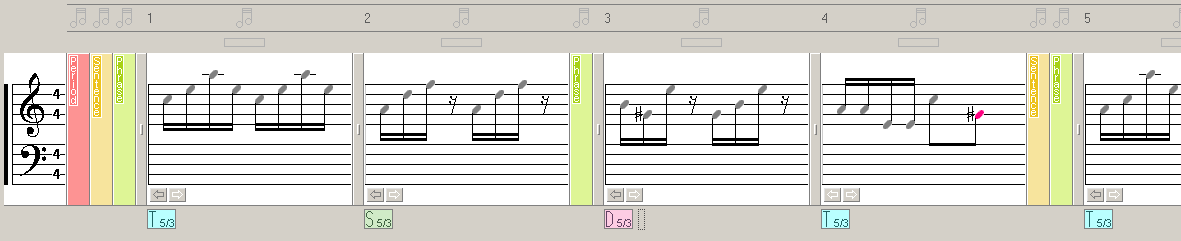
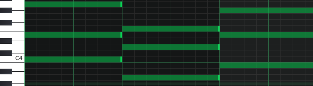
Here's how the script works. It accepts two tracks. The chord track and the template track. The chord track can be imported from Palette MCT. And I'd manually come up with the template track. That's easy, tho. I'd just make a small section of the pattern and do copy and paste. Here's an example. The top one is the chord, and the bottom one is the template. It shows three different chords being played over time.
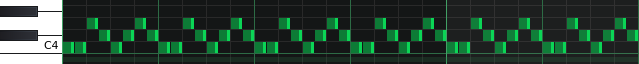
After running the script, this arpeggio track would be generated:
Notice how the template pattern track had followed the chord. When there're a lot of chords, this tool saves me a lot of time. It also eliminates manual handling errors.
I didn't mention this script in the Global Game Jam blogpost last year. Anyway, this tool was developed before the last year's game jam. Somehow it's still useful in this year. :)
The sound synth (instruments) were chosen from the default presets, which was further modified manually until it sounded right to me. Then I just threw in the arpeggio notes or bass notes or melody notes or chord notes for each of the sound synth and that's it!
And now I've got a 12.8 seconds of loopable music! :)
Needless to say, 12.8 seconds is far too short. :(
So I repeated what I did. I composed another piece of chords and melody using Palette MCT again, and export it to LMMS for further processing and put it at the end of the original composition. Now I've doubled the music length to 25.6 seconds. Anyway, here's the intermediate product of Palette MCT for the second piece:
Up till this point, the composition was in minor scale. For the third piece, I was thinking if I should try adding a major scale piece into the composition. That'd make the composition contains both minor scale part and major scale part. I've never done that before. And it seemed to me that that could be interesting. And I've already got 25.6 seconds. In case it doesn't sound right, I'd just scape the major part and keep the 25.6 seconds minor part. That's still good enough.
So here it goes. I repeated what I did, except that this time I composed a new 12.8 seconds piece in major scale instead of minor scale. Here's the intermediate product:
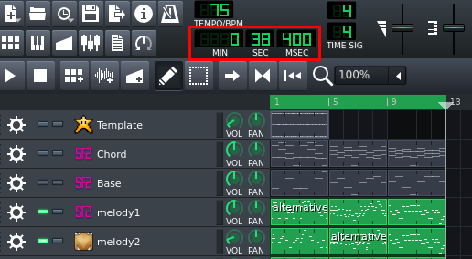
I further processed this third piece with LMMS. Then I put this part into the beginning of the composition. To my surprise, it actually sounded pretty good. Now I've got 38.4 seconds of music. :) The next step was to remaster it.
At this time, the music was mostly ready. I just needed to remaster it to make it sounds even better! One of the keys of making a piece of music sound nice is to make its tracks more diverse. I did three things.
The first thing I did was to reduce the volume of part of some of the tracks.
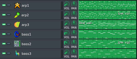
Please notice that the middle part hasn't got any track with volume reduced. That's because it's the climax of the music.
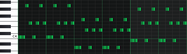
The second thing I did was that I built something that I'd call "alternative melody". I've no idea on the proper musical terminology for this thing. It's basically a variant of the original melody that's played at the same time as the original one. Here's how I did it:
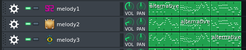
As shown above, at each instance of time, there're always two variants of melody being played. Two of the tracks are the main melody, with one of the tracks using an alternative melody. Since variety is crucial, I spread the alternative melody into three different tracks depending on the time of the music being played.
The third thing I did was that, I put in a reverb effect to the entire composition. It'd produce an illusion that the music is played from a different environment, like the size of the room, the audio-reflection property of the wall, etc.
And here's the final result with all tracks combined!
Now I've got the music ready. All I needed to do is to send the tracks to the programmer.
After discussion with the programmer, it's decided that the preferred amount of tracks is 7.
I'd have to make the tracks in a way that it'd loop seamlessly. It was dead simple. Here's how I did that. First, I exported the track. Then I take note of the time it takes for the music to wrap to the beginning.
According to LMMS, the wrap time is 38.4 seconds. It means that the last note is released at 38.4 second. Since the instrument sound doesn't stop immediately after the note is released, some special handling is needed to make the music seamless. Therefore, I used Audacity to do this:
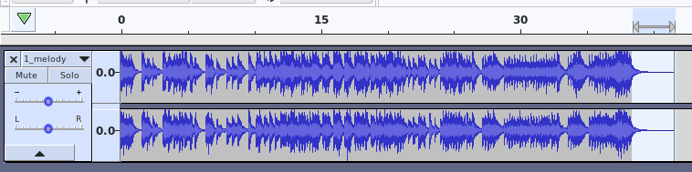
What I did was to cut the part after 38.4 seconds and move it to the front as a new track. Then I mixed the original track and the new track and there we have a piece of seamless audio! :)
But hey... There're 7 tracks. Of course I'm not going to do that manually! So I've made a shell script to automate the process with SoX instead of Audacity. It worked like a charm!
Then I converted the tracks to MP3 format using shell script. And I stumbled into a problem. Due to the nature of MP3 format, there's always a split second right at the beginning of the audio that no sound is being played, which would make it impossible to make seamless audio with MP3!
After discussing with the programmer, we've found that OGG is the go-to format instead of MP3. So we used OGG instead of MP3.
I sent the programmer the 7 OGG tracks, and my mission had been accomplished! And I went home.
And I was very glad that my teammates were happy with my music. I was also very happy with the artwork of the 2D and 3D artists. Of course, the program was also working great. :)
By the way, something rather funny happened during this day. The site we've joined was in Cyberport. During some time of this day, a staff of the jam site stood on the stage and announced this in English: "Hey guys. We've got a bad news. We've used up all of the water in Cyberport." It wasn't very funny until he repeated that in Cantonese. "成個數碼港D水俾我地飲哂喇!", which roughly translates to "All of the water in the entire Cyberport was completely drunk by us! Oh noes!" That's when everyone in the room were laughing. Those who couldn't speak Cantonese were confused about what's so funny.
We were told to purchase the water from a supermarket nearby. So we did that. Then we had dinner at a restaurant. When we came back and we noticed that there was still some water. Well, we had no idea on where they managed to get the water. Had we known this, we wouldn't have purchased the water.
This day was rather relaxing. All of my stuffs were done. The 2D artist was working on the video. And apparently, the 3D artist were working on graphic and probably also a bit of programming. I didn't asked about the exact split of work, tho.
Since I've got nothing better to do on the music, I decided to help on the programming. I polished the character movement. The original character movement relied on the system keypress. That isn't a good idea because the movement speed of the character would depend on the system keyboard configuration. If the repeat key interval is set to short, the character would move faster.
As I thought that the main programmer had nothing to do, I did the fix and showed it to her. It seems that there're some issues with the character sprite cycle. So we decided not to make the change.
Later I'd noticed that the main programmer were still working. She was working on the crystal collection counter. I felt bad for disturbing her while she was working on something far more important than character movement.
As the 3D artist and the main programmer are tourists, they'd like to stroll nearby. And they were away. However, there was still a little bit of time left. I asked if there's anything I could still do, and I found that the dialog boxes at the beginning of the game and the end of the game weren't implemented.
I asked if the code on the github repo were the latest one with instant messenger and asked if they're ok with me to implement the dialog boxes. I got a green light and I started working. That was an easy one. I pushed it to repo and they deployed it and that's it.
So we've got a working game with in-game objective (collect crystals) and an ending (a couple of dialog boxes). The game isn't particularly fun to play. But still, it looked real good. And the music's also a nice one (self-flattering.pdf)! The trailer looked good too.
As usual, there's a lengthy trailer-watching session for the jam. Each of us have a minute in maximum. Somehow there aren't as much funny vid this year compared with previous years.
And I've found a game that's about bird pooping on people during the session. That totally reminded me of my Poopie game. :D
After the session, each jammers were allowed to cast a vote. One of our team members had voted for our own game. Too bad! We failed to get the most votes. All of our team members should have voted for our own one! :P
This one is literally the best Global Game Jam I've ever had. It's just wonderful. It isn't like any Global Game Jam I've ever had before! Let's have a review of what the previous game jams were like to me:
For the first year, I joined the jam without a team. I expected that my skill would be put well-utilized. I even prepared by practicing using a game development library. It didn't end up to be of any use at all. It was a big team with multiple "game designers". I was rather pissed off of being forced to use a library that none of the team members was familiar with. The funny thing was that this thing was decided by a game designer. I was like "hey! Choice of library is none of your business". First mistake: I should have left the team right after that decision.
And I decided to sleep on-site to get the full experience of the game jam. Before the jam, I've asked those random internet people who had joined Global Game Jam. I was told that it's alright to sleep on site. It turned out that it just didn't work to me. I couldn't get asleep. Funny enough, I somehow decided to sleep on the site for the second night even I failed to get asleep at the first night! I shouldn't have done that at all! Second mistake: Decided to sleep on the site.
Since I couldn't sleep well, I couldn't make much contribution to the team either. I was exhausted.
Result? A broken game with 2-week of illness taking away my entire Chinese new year vacation! I'd call it a FUBAR! :(
Here's a link to my blogpost of Global Game Jam 2016 which you probably aren't interested in. There's a lot of grammar mistakes because I was sick by the time I wrote that blogpost.
Compared with the first one, this one was a fun one. It's nowhere as fun as the one of this year, tho. I joined the jam with a purpose. So I decided to jam alone. In fact, I pretty much had to because the jam was a part of my graduation thesis of an independent project. If I had a team, the college may take it that I'm not working on the independent project by myself. That'd be a problem. :(
I managed to complete the game. It's a game that's playable by dialing a phone number. It's possibly the first of this kind in Global Game Jam around the world. Despite that the technology used is rather advance, like utilizing text-to-speech and having a hardware device, the end result wasn't that good. The sound synth was simply too bad. I should have recorded the audio clips with my voice instead of using text-to-speech.
Anyway, I was happy enough because I got the game completed. :) But I did feel a bit lonely. :(
Here's a link to my blogpost of Global Game Jam 2017 which you probably aren't interested in.
(If you're the producer of the game "Carpe diem" in Global Game Jam 2018, I hope that you'd never read this. This section is probably super cringy to you. I'm sorry.)
This is my first game jam that I had joined a team without screwing up. I was the musical guy of the team.
The main problem I had with this game jam was that there's an idea person who basically did almost nothing productive other than quality control. Most of the time he was just surfing the net with his laptop and his smartphone at the same time! If I remember correctly, he also had a tablet. I've never seen anyone being able to do this level of multitasking before. Anyway, in some other times, he was looking for information about making an awesome game or making an awesome trailer.
Apparently, the team members of the team I joined were from the same company. I was the only outsider. I'd imagine that the idea person would be in a superior position in the company that he was working for.
I spent quite a bit amount of work on a piece of music. I showed it to him and he just rejected it straight away and provided some not-so-helpful instruction. This was the thing that I had problem with. Here's what I thought: "Hey! You did nothing. How come you'd criticize my work? You're worse off." Of course I didn't spout that out! I redid the music and sent him another piece of music anyway. It seemed to me that he still wasn't satisfied. But he compromised and said that it was ok. Well, I guess that's good.
Right before the jam ended, we were filling in the project page on the Global Game Jam website. Surprise! The title that the idea person was getting was "Producer". It's very laughable. If I don't laugh, I'd cry! xD
Anyway, we still managed to complete the game, sort of. I only got to play the game after the jam. It sucked. :P
By the way, I've chatted with a parallel team right before the end of the jam. Apparently their team doesn't have a quality control person nor an idea person at all!
Here's a link to my blogpost of Global Game Jam 2018 which you probably aren't interested in.
After reading the flashbacks, now you understand why this Global Game Jam is the best one that I've had!
I didn't jam alone. There's no "team leader" nor "producer" nor "director" nor "quality control" guys in the team. We don't have any quality standard for the game. We just put in whatever we've got and contributed to the team. We just took whatever available from other team members. Every team member didn't really care about the art style nor music style nor we'd judge the programming framework or technique used. That made the game jam really, really awesome. After this jam, I think this is really how a game jam meant to be. I guess the guy in parallel team I've chatted with last year was having a similar awesome experience as I have this year. Perhaps I was just being extremely unlucky that I joined wrong teams for years that made me unable to enjoy the jam to the fullest!
Here, I'd like to take the chance to thanks all of the team members. Thank you very much for making this jam the best one in my life, ever! You guys are awesome. And here's a list of the team members:
You can find the website of Kirill and Sneha here on Codercat.tk, which contains a lot of awesome web-based projects! Most of their projects are utilizing WebGL. Even the playable of this game jam is hosted on this site. Do check out their website!
Also, do follow @_jintii on twitter! She's real good at drawing 2D arts, especially in anime art style! nya~ :3
As of the time of writing, despite that I can write English pretty well, my spoken English is only conversational. I'm very well aware of this problem since forever ago. And those random tourists in the team I joined couldn't speak Cantonese. I had no choice but to speak English! >_<
My spoken English is good enough for project communication, not smoothly, tho. Anyway, I'm glad that I started watching anime daily in English dub since about a year ago (I watched it in sub before that). My spoken English had went from almost-non-working to semi-working. But I still need to further up it somehow. That'll take quite a bit of time. Oh well, let's wait and see.
Uh oh. So what about the game console...? Now I've got 5 units of assembled game consoles and three ST-Link programmers laying around:
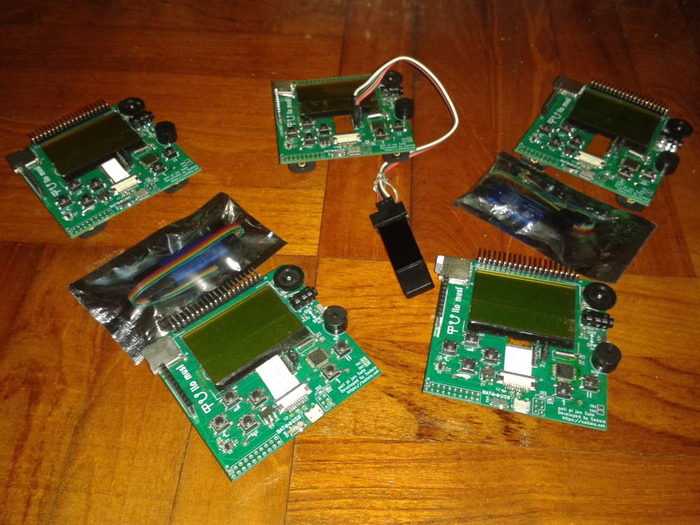
(Yes, we've now got PCB for the game console since like a few months ago. I still haven't got the time to blog about this update)
Oh well. Now I've got a problem. What to do with all these game consoles?
I guess I'll save two units and a programmer for myself. And I promised to send a unit with a programmer to someone in India. That'd get rid of 3 units and a couple of ST-Link programmers.
And I've still got two units and a programmer to go. I don't know. Perhaps I could do a giveaway. Maybe I could give them to Ludum Dare participants so that they can make games with this game console.
In fact, thanks to the judges of the sponsors appreciating the art style, each of our team members had managed to obtain an extra unit of electronic waste. It's a Google Home Mini. I think the artists (Jintii and Kirill) deserve the most credit for this one. And the main programmer (Sneha) also deserves quite a bit of credit because she made the game functional. And I, uhm, I just got the Google Home Mini anyway. xD I'm pretty sure that this thingie would still get awarded if they were using random music found in the internet instead of using mine. :P
At least I have some idea on how to handle the game console units. As for the Google Home Mini, it really beats me. I thought about selling it. But it seems that it's only worth like $30~40. It makes this option not very attractive. It isn't very useful to me either. I've absolutely have no idea on what to do with it at all. Oh well, I guess that's "what home means to me". It's an electronic junkyard. :/
Please do not join game jams just to criticize works of other team members. We aren't paid to work on the game. If you intend to join a jam and do that to us, I guess you better not to join or you'll be hated. Don't get me wrong, your talent could be much better utilized in corporate world. Your skill could be used for making a lot of money for the company that you're working for. But if you don't have any technical skill and nitpick stuffs that other team members come up with, frankly, game jam really isn't for you.
nimi mute ni pi toki pona li lon. o pilin e ni.
Good news guys! The Ilo Nanpa project is completed! It's a calculator for Toki Pona numeral.
Media coverage:
Toki Pona is a minimalist constructed language invented by jan Sonja. It has less than 130 words. It has an obscure numbering system.
Unlike the numeral of most languages, Toki Pona Numeral is a not a base-10 numeral system. There're two numbering system in Toki Pona, they are the simple system and the complex system. Here's the simple one:
Obviously there's no point making a calculator for the simple system. Here's how the complex system work. It's similar to coin-counting. Numbers are made up by adding up existing numeral words as follows:
For example, 37 would be mute luka luka luka tu because 20+5+5+5+2 is 37.
This Ilo Nanpa calculator is designed for working with the complex numbering system of Toki Pona.
Ilo Nanpa has the following feature:
Ilo Nanpa has 16 LEDs, 9 push buttons, an en/weka (addition/subtraction) slider switch and a power slider switch. A photo of Ilo Nanpa is shown below:

The power slider switch can be used for switching between battery power and USB power. To power off the device, remove the USB and slide the slider switch to the USB position. Alternatively, remove a battery and slide the slider switch to the battery position.
As shown above, it has an LED for "weka anu ala" (negative or zero), an LED for "wan" (1), a couple LEDs for "tu" (2), three LEDs for "luka" (5), four LEDs for "mute" (20), an LED for "ali" (100), a couple of LEDs for "ali ali" (200), and a couple of LEDs for "ali ali ali ali ali" (500).
Reading the number is rather straight forward. You just add up the numbers of the lit LEDs and that's it. For example, if three "mute", two "luka", a "tu" and a "wan" lights up, that'd make "mute mute mute luka luka tu wan", which is 73. If an "ali ali ali ali ali", an "ali ali" and a "wan" lights up, that'd make "ali ali ali ali ali ali ali wan", which is 701.
If the displayed value is zero, only "weka anu ala" would be lit. For negative numbers, the shown LED would be the same as positive number, except that the LED "weka anu ala" would also be lit.
There're nine buttons (ala, wan, tu, luka, mute, ali, pana, kama, tenpo) and an en/weka (addition/subtraction) slider switch. They're used for operating Ilo Nanpa.
Resetting the value to zero - ala button
The "ala" button resets the current number to zero.
Performing Addition and Subtraction Operations - wan, tu, luka, mute, ali buttons
The buttons "wan", "tu", "luka", "mute", "ali" behaves in this way: When the slider switch is in "en" (addition) position, the button pressed would add its value to the current value. When the slider switch is in "weka" (subtraction) position, the current value would be subtracted from the value of the pressed button.
This design makes sense in Toki Pona numeral because, for example, when you're trying to add 31 to the current value, as 31 is "mute luka luka wan", you'd just slide the slider switch to "en" position and press "mute", then "luka", then "luka", then "wan". If you want to further add 3 to that number, you'd just press "tu" then "wan" after that. If you want to subtract a number from current value, you'd slide to "weka" position and type in the number with the buttons.
Saving and Loading Value - pana, kama buttons
The "pana" button saves the current value displayed on LED. The "kama" button behaves like the "wan", "tu", "luka", "mute" and "ali" buttons, except that it adds or subtracts the current value with the previously saved value depending on the slider position.
Multiplication can be performed by using "pana" and "kama" buttons. For example, if you want to compute 137x5, first you resets the value to zero using "ala". Then you slide the slider switch to "en" position. After that, you type in 137. Then you press "pana". Then you press "kama" four times, which is one time less than the desired multiplier. And you'd get "ali ali ali ali ali ali mute mute mute mute luka", which is 685.
The saved value of "pana" persists over power cycles.
Stopwatch and Timer - tenpo button
This is the most complicated function of Ilo Nanpa. For simplicity, let's consider only positive value for now. I'll cover negative value later.
After the "tenpo" button is pressed, Ilo Nanpa would enter timing mode. It adds or subtracts the current value by one for each second elapsed, depending on the position of en/weka slider when the timing mode started.
During timing mode: pressing "wan", "tu", "luka", "mute", "ali" and "kama" would have no effect. Pressing "tenpo" would leave timing mode without doing anything to the current value. Pressing "ala" would leave timing mode and reset the value to the one before entering timing mode. Pressing "pana" would save the current value without leaving timing mode.
If you're using Ilo Nanpa as a timer, it would be counting towards zero. When zero is reached, it would stop the timing and the "weka anu ala" LED would blink. The brightness of the LED would be higher than usual. Pressing either "tenpo" or "ala" would leave timing mode and reset the value to the one before entering timing mode. Pressing "pana" would save the current value, which is zero. Pressing all other buttons would have no effect.
If you're using Ilo Nanpa as a stopwatch, it would be counting towards the limit (i.e. 1600 for positive number). When the limit had reached, it would stop timing and the LEDs would show the limit value and blink. The brightness of the LEDs would be higher than usual. The behavior of all buttons are the same as the one during timing mode.
If timing mode is performed with a negative value, the value update would perform 20x faster, which means that the value would get updated for every 0.05 seconds instead of every 1 second. Other than that, the behavior are the same for positive and negative value.
UPDATE : some info in this section is outdated, including production time and the way to obtain a unit of this device. Please refer to this new blogpost for the updated info: Future Distribution of Ilo Nanpa with Time-Efficient Production Method
I'm interested in distributing this Ilo Nanpa device to Toki Pona speakers.
The material cost is cheap. It only costs around $5 for a unit, including shipping fee to my home. The shipping cost to the recipient would costs <$5. However, it takes me 2 hours to manually produce a unit of Ilo Nanpa, including soldering, flashing the program and quality control. That's a lot of work for producing each unit.
If you're interested in getting an Ilo Nanpa, please fill in the form in the official website of Ilo Nanpa. At this stage, I only offer this device to Toki Pona speakers. I'll personally verify if you're capable for written communication using Toki Pona by using the contact methods you provide in the form. I ask about how much you're willing to donate in the form. It's ok to fill in any amount. At this stage I mainly want to estimate the demand and the amount that the recipients are willing to donate. If you don't have any spare money, don't be ashamed to fill in 0 there. Just tell me your situation in the "sina wile toki e ijo ante, la o toki tawa mi kepeken lupa nimi ni:" text box and there's still a chance that you may get one. :) No commitment is needed to fill in the donation amount. It's understandable that one may change their mind on the amount to be donated. However, please do not deliberately lie because that would screw up my budget.
If you have the money, please kindly donate some to me as it takes a lot of time to develop and produce this device. The extra money will be used for sending units to those who're donating less, or who have no spare money to donate.
I'm not sure about the total demand of this device. If the demand is small (maybe less than 10 units), I'd be happy to manually produce the units as long as I can recover the shipping cost and material cost.
It'd be very embarrassing if the demand is between 10 units and 50 units. There's no way that I'd go for mass production, and it wouldn't be fair for me to do the work with zero labor cost. If the demand is somewhere in between 10~50 units, I'd like to get $40 for my two hours of work (shipping fee and material cost not included), which is quite expensive and I doubt anyone would be willing to spend this amount of money for this simple device. :( I don't know. Perhaps I could get another Toki Pona speaker to share the workload and help doing the soldering and send the device to other Toki Pona speakers. Of course, anyone doing that would get a share of donation for the units that they've soldered. Please contact me (Sadale) on the Toki Pona IRC channel if you're interested in helping.
If the demand is high (perhaps more 50 units), I'd possibly pay a PCB assembly to do that for me, maybe I can start a crowdfunding campaign for that. Anyway, it may not be easy to get a PCB assembly to produce this device. Unlike conventional electronic devices, this device uses unusual electronic designators. Conventionally, resistors are labeled as R1, R2, R3... Capacitors are C1, C2... LEDs or diodes are D1, D2... For this device, resistors are awen1, awen2... Capacitors are wawa1, wawa2... and LEDs are suno1, suno2... This can be a problem for PCB assembly to produce it. If I go for mass production, perhaps I have to do a bit of compromise on the designator names.
If you're interested in getting a development kit, and you're willing to cover the material and shipping fee, I'd be more than happy to send you one. That's because most of the time involved in distributing the device are spent on soldering. It'd be a good thing if you're willing to do that on your own. Of course, I'd even be happier if you're donating a bit extra for the development effort. :P Almost all components of the device are the SMD ones. Fortunately, most of them doesn't have small pitch. The only difficult part is the USB port having a pitch of around 0.65mm. The microcontroller is having a pitch of 1.27mm, which isn't difficult. Other than that, there're just a lot of 0603 components, some SMD buttons, a 3-pin male header, a battery holder and a couple of mini slider switches. They aren't difficult (to me :P) to solder at all. I'll also ship a programmer to you so that you can program the microcontroller.
The objective of this project is to experiment with working with low-end microcontroller. After some research, it's found that STM8S001J3 is one of the cheapest microcontroller in the market with a cost of only $0.2 per unit at a quantity of 10k. This microcontroller has nice amount of flash, RAM, EEPROM and peripheral. It has 8kB flash, 1kB RAM, 128 bytes EEPROM. Compared with microcontroller series like the ATTiny or the PIC ones, this one is both cheaper and better. The only shortcoming of this microcontroller I've found is the voltage range. It's a bit narrow compared with other low-end microcontrollers.
STM8S001J3 only has 8 pins, with 5 IO pins. They have another model that's a bit more expensive with 20 pins. I intentionally pick the 8 pins one to practice IO multiplexing.
Technical objective aside, this would probably be the first electronic device designed for Toki Pona language in mind.
The most interesting aspect of this project is that the microcontroller only has 5 IO pins, yet it's capable for interfacing with 16 LEDs, 9 push buttons and a slider switch. One of the 5 IO pins doesn't even have push-pull output capability. It makes the project even more challenging.
The schematics of the project is shown below. Click the image to open it in a new window:

Charlieplexing is a technique of multiplexing output pins for driving many LEDs with small number of pins.
Conventionally, an output pin can only have two states, they're either high or low. Pins on modern microcontroller often have one more state in addition of the two states, which is high-impedance state. In high-impedance state, the pin behaves as if it's disconnected from the circuit.
To perform Charlieplexing, one would list out all of the possible pin pairs of all available pins to be used for driving LEDs. For example, if I have 5 LED pins, A, B, C, D and E, the pin pairs would be AB, AC, AD, AE, BC, BD, BE, CD, CE and DE. After that, we connect two LEDs to each pin pairs. One of them is forward-biased. Another of them is reverse-biased. Since there're 10 pin pairs, 5 pins would be able to drive 10x2 = 20 LEDs.
To light up an LED, we'd set all irrelevant pin to high-impedance state, which "disconnects" the pins from the circuit. After that, we set a pin to high, another pin to low, then the desired LED would be lighted up. For example, if you wish to light up the reverse-biased LED connected to the AB pin pair, set pin C, D and E to high-impedance, then set pin B to high and pin A to low. Then the LED would light up.
For this particular microcontroller, one of the pins is not capable for high-sink output. It means that it is not possible to output the kind of high signal that's required for Charlieplexing. That would take away 4 LEDs. Therefore, this device has 16 LEDs instead of 20 LEDs.
For this device, one LED is lighted up at a time. Then it switches to another one. This continues and repeats. At high switching frequency, it gives the user an illusion of multiple LEDs being lit at the same time.
The input buttons are multiplexed using voltage divider. There're 9 buttons and a slider switch.
The slider switch is attached to a dedicated pin. One of its position is connected to Vcc via a 470k resistor. Another of them is connected to ground via a 470k resistor. A high resistance is chosen to minimize the interference with the LED circuit.
For the 9 buttons, they're divided into three groups. Each group is having three buttons. The first group is ala-wan-tu. The second group is luka-mute-ali. The third group is pana-kama-tenpo. Each group is connected to an ADC pin of the microcontroller.
The microcontroller has two pins connected to ADC out of the box. To connect the third pin to ADC, an option byte has to be programmed. With three ADC-capable pins, we can have three button groups each handling three buttons.
Each ADC pin is pulled down by a 470k resistor. A high value resistor is chosen so that it would minimize the interference with the LED circuit. When a button is pressed, the ADC pin is parallelly connected to Vcc via a 10k (ala/luka/pana), 10k+20k (wan/mute/kama), or 10k+20k+20k (tu/ali/tenpo) resistors. Holding any button would cause the Vcc resistor and the pull down resistor to form a voltage divider. The reading of the voltage divider is fed to the ADC pin of the button group. The value chosen on the Vcc side is significantly lower than the pull-down side because there's a limit of input impedance of the microcontroller. If the is input impedance is too high, the ADC wouldn't work.
Is it alright to share the same IO pin for both input and output? Yes, it is. But it's more complicated than I thought. I ran into a few issues due to the sharing of input and output pins.
Button Detection Issue
I thought that the ADC reading for each button group would simply be a voltage divider as long as I've set all output pins to high impedance state. For example, pressing "ala" would makes the ADC reading to be MAX_ADC_VALUE x 10k/(470k+10k), pressing "wan" would be MAX_ADC_VALUE x 30k/(470k+30k) and pressing "tu" would be MAX_ADC_VALUE x 50k/(470k+50k). I was mistaken.
This thought is wrong because it doesn't consider that the input pins and the output pins are sharing the same pin. It means that when a button is pressed, the Vcc connected to the 10k/30k/50k resistor would get to the ground via both the pull-down resistor of its own button group and other button groups via the Charlieplexed LED network. That's because the Charlieplexed LED network is connected to all button groups, which is pulled down to the ground. In addition, the en/weka slider is also connected to the Charlieplexed LED network. All of these would affect the ADC reading.
Due to manufacturing tolerance, the forward voltage of each LED on the Charlieplexed LED is not known. Therefore, there's no easy way to calculate the value of ADC reading when a button is pressed. For this reason, I've included ADC reading calibration mechanism in the factory mode of the firmware.
The ADC calibration scene would require the user to press a button. It records the ADC reading of the button. The operator is required to press each of the buttons for a few times. The ADC readings of each button press are averaged out and the ADC threshold values for each button are calculated and they're saved to the EEPROM of the microcontroller. After the calibration, the microcontroller is ready for detecting button presses.
It's empirically determined that the effects of holding buttons of other button groups is negligible to the ADC reading. However, the en/weka slider does have substantial effect to the ADC reading. For this reason the ADC reading calibration are to be performed for both "en" slider position and "weka" slider position.
en/weka Slider Detection Issue
Unlike other buttons, this slider is connected to either Vcc or Ground via a 470k resistor. As the resistance is high, lighting up any LED or pressing any button would affect the detection of en/weka slider for a while. For this reason, the firmware is designed in a way that it won't perform en/weka detection when any button is held. It also stops lighting up the LEDs for a short time once a while for detection of en/weka slider position.
LED display issue
Holding a button would connect Vcc to the LED network with a resistance of 10k/30k/50k. That causes some LEDs to light up.
As a workaround, a model of LED with lower brightness is chosen. It's empirically found that the one with lower brightness is less vulnerable to this issue. With this kind of LED, the brightness caused by pressing button is far lower than the LEDs lit by the display of number. Therefore, it wouldn't be a problem for normal operation at all.
Way to Go!
Since all these issues have got a solution, there isn't a problem anymore. The device works with input and output pins multiplexed! I managed to get 5 IO pins to control 16 LEDs plus 9 buttons plus a slider switch! :D
Factory mode can perform ADC reading calibration as mentioned above. In addition of that, it's possible to perform key press tests and LED brightness adjustment using this mode.
To enter factory mode, hold down "ala" on power up for 5 seconds. After that, three "mute" LEDs and the "ali" LED would light up. It means that the device is now in password mode. By pushing the correct button sequence, the user would enter factory mode. If the user had typed in a wrong button sequence, he'd be led to normal mode. This design is to prevent unintentional access of factory mode. That's because if the user had mistakenly entered factory mode, he could screw up the ADC calibration values, which would break the button detection mechanism of the device until a proper recalibration.
Please refer to the README file of official Github repository of Ilo Nanpa for understanding how to work with factory mode.
Since we've got a low pin count microcontroller, we couldn't dedicate a pin for programming and debugging. The programming pin shares the same IO pin as luka-mute-ali button group and a few LEDs. This is a problem because we need a mechanism to reprogram the microcontroller in case it's needed.
To get the microcontroller to stay in programming mode, hold "pana" key on power up. As long as the button is held, the device would stay in programming mode. Once it's release, it'd enter normal operation mode.
The pana-kama-tenpo button group is intentionally chosen as the programming button. That's because it's a bad idea to pick any other button groups. The luka-mute-ali button group is shared with the programming pin, which means that holding only of these buttons may affect the signal of programming pin. The ADC of ala-wan-tu button group is only available after the option bytes are programmed. In case the engineer had forgot to program the option bytes, the button press of ala-wan-tu wouldn't get detected. That would cause the microcontroller to get locked up and it wouldn't be possible to reprogram it anymore.
Since using any of the other button groups is a bad idea, the pana-kama-tenpo group is chosen as the programming button group.
Let's not worry about debugging. It just isn't possible to spare a pin for debugging, unfortunately.
By the way, when I was trying to implement this mode, I screwed up a few times and permanently locked up a couple of microcontrollers. I had to throw them away and solder a new microcontroller onto the PCB. :(
This is the second PCB I've designed. The first one was for ilo musi (the game console that I had been developing). In fact, the third prototype of ilo musi is mostly completed. It's soldered on a PCB. I've never got the time to blog about it, tho.
The PCB was designed using KiCad. I use it mainly because it's free. As a bonus, it's open source. :)
The PCB of Ilo Nanpa is 50mmx50mm. I keep it small because some PCB fab offers a cheaper price for 50mmx50mm boards. I ordered 10 boards for $4 (shipping fee not included), and somehow they delivered 18 boards to me. :D
The PCB is a double layer one. There's a layer on the frontside of the board and another layer on the backside.
Other than that, there's nothing very interesting about the PCB of this project.
I've learned quite a lot from this Ilo Nanpa project, including:
This is also my first completed electronic project having a PCB! :)
Now the Ilo Nanpa project is officially completed. All I need to do is to distribute the device. :)
I'll continue to work on ilo musi, which is the game console project that I had been working on and blogging about. See you!
Hey guys! I've developed a game in 48 hours for the game console that I have been working on lately!
The following Youtube video contains all of the info about the gameplay as well as a bit info about how this game were made. Please do watch it! :)
Links: Source code (Github) | Alakajam Entry Page
It isn't possible to develop a game within 48 hours without any preparation work. Therefore, I did spend quite a bit of time on preparing it. The preparation includes:
I wish I could get a third party to review this game. Unfortunately, it isn't possible for anyone else to play this game for now because the game console isn't released yet. So here's my self-review of this game.
As a game developed within 48 hours, I'm rather satisfied with the result. Thanks to my preparation work as well as my previous experience on game jams, I'm able to finish this game on time.
The game is rather challenging and well-balanced. The game is made interesting by having the player keeps try picking up coins. That's the only way to score in the game. For each coin the player had picked up, the game gets a little bit more difficult until the player couldn't hang in there and lose the game. With randomization of various elements in the game, including the spawn rate of conveyors and hostile entities, the position of the objects, etc. The difficulty of the game is partly based on the luck of the player. That makes it a fun game for players with any level of gaming skill.
For the program of the game, it's rather sad that there's quite a bit of code duplication in the game. That's partly because I'm on a memory-constrained system. Another reason is that there's a time limit for the jam. Anyway, the game jam had ended. I'm not going to fix that. :P
This game demonstrates that the game console I'm developing is capable for running games! It shows the system API of the game console is good enough for game development. Therefore, I am able to move forward to further develop this game console. In the future, this game console might become an alternative to PICO8 for game jams participants.
I'm sorry that I didn't update about the progress of the development of the game console for a while. A lot of progress were being made lately!
The second prototype of the game console is ready! It's soldered on a perfboard. There're a few upgrades made in this new prototype. Here's the specs of the second prototype:
left, right, up, down, button 1 and button 2The PCB to be designed will be based on this second prototype.
Despite that I had professional experience in embedded programming, I'm rather green. Therefore, I've discussed with some veterans in embedded programming about the design of this game console. Since this game console works by loading the game from SD card to the internal flash of the microcontroller by self-flashing, they immediately pointed out that performing frequent self-flashing would wear off the flash of the game console quickly.
I've checked the datasheet of STM32F030K6T6. The guaranteed number of flash write cycles is merely 1000 cycles. That's a little bit small and it will cause problem to our game console. Interestingly, the 1000 number of write cycles is "Guaranteed by design, not tested in production". For other microcontrollers produced by STMicroelectronics, the number of write cycles is often 10000 and it's "Guaranteed based on test during characterization".
It just doesn't make much sense to have this little number of write cycles. Here're some theories I have about the number:
In long run, maybe I should do my own research on figuring out the actual number of flash write cycles of the microcontroller I'm using. I refuse to believe that the write cycle is 1000 cycles in room temperature. If the write cycle is like 3000 cycles, it's kinda acceptable because that'd mean that the user can load 10 games every single day for 300 days until the game console breaks. And I doubt that there's such an enthusiastic player of this game console anyway. But 1000 cycles is really a bit too little.
To reduce the number of flash write cycles, I've modified the bootloader firmware so that it only perform flash erase and rewrite if the source ROM on SD card is different from the previousy self-flashed game inside the microcontroller flash. That would cause self-flashing not to be performed if the same game is launched again after a reboot. This should help reducing the flash writes by quite a bit, especially if the player is repeatedly playing the same game over and over again.
Another issue that those professionals pointed out was the Game Flash and RAM Offset. They raised an interesting idea about the offset of Flash and RAM.
In the past, I designed the Flash and RAM layout like this:
There's a huge problem with this design. For the flash, if I ever update the firmware and the size of the firmware got increased, that would cause the offset of the Game Flash to be changed. That'd require the game to be rebuilt to work on the newer version of the game console. The same issue goes for the RAM.
Therefore, I've modified the layout. Now it looks like this:
For the Game RAM, I put the bootloader-exclusive RAM at the end. This design allows the bootloader RAM to expand without changing the origin offset of the Game RAM. In addition, if I ever upgrade to a microcontroller with more RAM, the entire RAM space would be expanded. And I would push the Bootloader RAM to the end of the RAM, and the Game RAM space would also be expanded. Since the origin of the Game RAM remains unchanged, I can still run the game that's built for the pre-upgrade version of the game console.
The same story goes for the flash. However, it's a bit more tricky because I need the bootloader to take the first sector of the Flash. That's because the first sector contains the interrupt vector and boot-related stuffs. I have to take the first sector so that the bootloader would be loaded on power up instead of the previously flashed game. Other than the first sector, the remaining part of the bootloader is put at the end of the flash space. That brings us the same advantage of putting the bootloader-exclusive RAM to the end.
This thing was done long time ago. But I've been too busy to blog about it. In the past, we made something called EXTIF to allow the game to call the functions located in bootloader by using a software interrupt, just like how BIOS work. It turns out that this design is utterly dumb because there's a function calling convention for ARM. It's called Procedure Call Standard for the ARM Architecture(AAPCS). As it's the go-to standard for functions compiled for ARM microcontrollers, it's possible to call any functions compiled by any compiler with any amount of parameters as long as you have the address of the functions.
For this reason, I just made a veneer on a fixed address for each of the system API functions. The veneer redirects the function call to the actual address of the function inside the bootloader. To call the system API function, the game declares all of the system API functions available in the bootloader and assign those fixed addresses of the veneer to the function declarations. With GCC, it's possible to map a function to an address by using the --just-symbols parameter when you invoke the linker.
The latest bootloader firmware is able to redirect almost all of the interrupts of the microcontroller to the Game ROM. A veneer interrupt handler were used for calling the interrupt handlers in the Game ROM. That enables the game developers of this game console to perform low-level programming. Along with the high level API inside the bootloader, this game console allows its game developers to learn about both higher level programming and low-level programming.
Here I've managed to complete the 4th Alakajam by developing a game for my game console. :)
Now that the firmware of the game console is ready. The next step of the development of this game console project is to design the PCB. After that, perhaps I'll also draw a case for the game console. If I have the time, perhaps I'd also develop an emulator for it. Since the microcontroller behind this game console is an ARM one, it should be possible to modify a Gameboy emulator for running games developed for this game console.
Just as I planned, I expect this project should be completed some time in 2019. Maybe the emulator would be available in 2020 if I end up working on one.
That's it for this blogpost. I'll update you guys soon! :)
As of 15th Oct 2018, I'm currently in between jobs. I was an embedded programmer of thermostats with a bit more than a year of experience. I did firmware development, Python automation scripts as well as tools for internal use, including setting up MQTT server and web server on a Raspberry Pi. In addition of that, I have been a hobbyist programmer for 9 years since I was back in middle school. Currently I plan to learn further about Python and modern web development technologies, mainly the back-end and devops ones. Then I'll start actively looking for another job. I prefer to go for a remote-working job. It can be full-time, part-time or freelancing.
If you're looking for someone to fill in any sort of programming-related positions, feel free to contact me via "hire dot me at sadale dot net". Alternatively, you can look for me on Freenode for having informal conversation with me. My nickname is "Sadale" there. Keep in mind that you have to identify (i.e. login) on Freenode in order to PM me. That's a new policy of Freenode to deal with the recent IRC spambots.